
 |
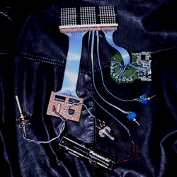
The SPIRIT EVM shown without an enclosure. Photo of finished product coming soon! |
EMF detectors typically indicate relative electromagnetic field strength at any given moment with a bargraph-type readout. This sort of readout is useful for measuring static electromagnetic fields, but less so when attempting to note a change in these ambient fields. The SPIRIT EVM is an EMF detector more suited to the ghost hunter.
It uses a two hundred LED (Light Emitting Diode) matrix to display relative electromagnetic field strength in a manner vaguely similar to an oscilloscope. By sweeping the ten-LED bargraph readout horizontally, a waveform of sorts is displayed (thanks to persistence of vision), showing variances in field strength as spikes on the graph.
The heart of the unit is the Electronic Goldmine's G8317 electromagnetic field detector, available via mail order for $8.95. (These units are surplus, and available in limited quantities. If you want to be able to follow these step-by-step construction plans, you should purchase one as soon as possible. This circuit could be adapted to work with other EMF detectors, however.) The G8317 electromagnetic field detector operates on 9-12 volts DC. It has a ten-LED bargraph-type display that indicates relative field strength and one LED that indicates circuit power-on status. A push-button power switch is mounted on the board.
The SPIRIT EVM design adds a two hundred LED display matrix and a display driver circuit.
The two hundred LED display matrix consists of six G7705 5x7 Red Dot Displays from the Electronics Goldmine. These units consist of thirty-five red LEDs arranged in seven rows of five LEDs. (This actually produces a display with 210 LEDs, but you can leave the extra ten unused.) There's no reason why you couldn't use two hundred individual red LEDs for the display if you wanted, but you would have a lot of extra work to do. The 5x7 Red Dot Displays have only fourteen pins each, making a total of eighty-four solder points; using individual red LEDs would increase this to four hundred solder points!
The display driver circuit is actually two 1-of-10 sequencers that drive the horizontal aspect of the display. The sequencers' speed is variable, making the display fairly versatile. Unfortunately, the simplistic design of the display driver results in two columns being lit at all times, so the display is actually two 10x10 readouts. The plans provided here could easily be altered to produce a single 1-of-10 sequencer to drive the display, and a smaller one hundred LED display, if the experimenter was so inclined. The original intention was to produce a single 1-of-20 sequencer, making the display a single 10x20 readout, but this turned out to be beyond the circuit design capablities of the author. (Perhaps a knowledgable reader can assist in the design of a more advanced display driver..?)
Admittedly, the construction process is pretty time-consuming for this project, but it is not particularly difficult. Patience and care are all that is required to build your own EVM.
--------------------
Tools List
Parts List
Circuit Schematic
Construction of the Display Matrix
Construction of the Display Driver
Modifying the G8317 EMF Detector
Final Assembly
--------------------
The construction details of the SPIRIT EVM are provided here for all to use in good faith. Please be careful with hot soldering irons and sharp razors; very real injury can result from carelessness. Neither SPIRIT nor its constituent members accept any responsibility for any accidental injury incurred in the process of completing this project. Just be careful, OK?