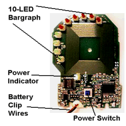


The G8317 EMF Detector has a ten-LED bargraph-type display. The display LEDs share a common annode (positive) connection. Their cathodes (negatives) are brought low by the circuit, depending upon the strength of any electromagnetic fields near the unit.
The ten display LEDs must be removed, along with the power indicator LED. The author found that by holding one of the LEDs tightly by its base using a pair of needlenose pliers and applying tension, he could heat the solder joints on the other side of the board and free the LED. Often, the LED had to be rocked back and forth while alternately heating the two solder joints for several minutes. Take your time and be careful not to apply too much heat to the circuitboard. Using a heat sink is always a good idea.
The battery clip must be removed also. The wires can be clipped easily, but the white silicon sealant connecting them to the circuitboard is more difficult to remove. Use a sharp hobby knife or razor to carefully scrape the sealant off of circuitboard, being very careful not to damage the circuit traces or the components on the board. Then, hold the wire ends with a pair of needlenose pliers and pull them gently while heating the solder joints on the other side of the board.
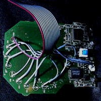
Next, trim a length of ribbon cable down to twelve conductors. These wires should be separated, stripped, and connected to the power, ground, and the cathode connections from which you removed the ten display LEDs.
Remember to turn the power switch on and leave it on!

The modified G8317, with display LEDs, power LED,
and battery clip removed, and ribbon cable connected.