

 Spring 2001 Update
The bulk of the electronic
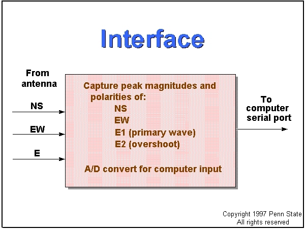
circuitry resides in the Interface unit usually placed nearby the display
computer. The
analog signals for the voltage, or e-field (E), and magnetic, or b-field (NS, EW), components are brought
to the Interface unit via coaxial cable.
 The Interface circuits capture and
digitize the peak magnitudes of the e-field and b-field signals
from the antenna array and send them to the serial port of the computer.
The e-field signal
is used to trigger the gate process for capturing the initial peak
magnitude and polarity (E1) of the e-field signal and for capturing the
peak magnitude and polarity (NS and EW) of the two b-field signals.
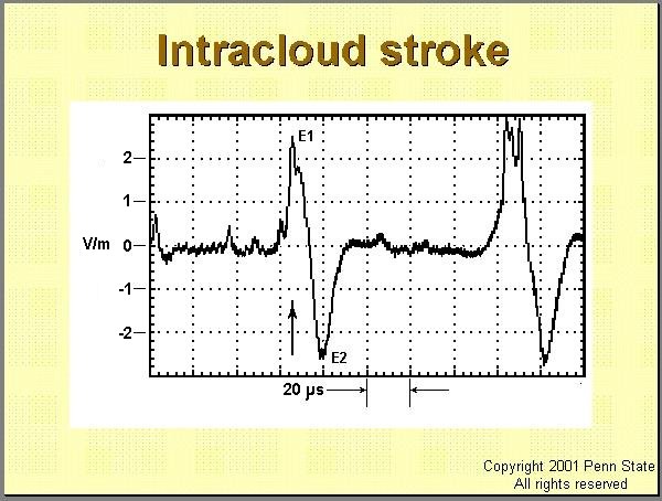
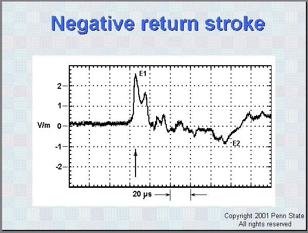
Any overshoot (E2) in the e-field is also captured. In the two waveforms below, the arrows denote the moment of initial peak capture.
 A successive pair of e-field waveforms
from intracloud strokes. The arrow indicates the moment the interface gate
opened and captured both the peak magnitude E1 of this signal and the simultaneous
NS and EW b-field signals.
 An e-field waveform from a negative
return stroke. The arrow indicates the moment the interface gate opened
and captured both the peak magnitude E1 of this signal and the simultaneous
NS and EW b-field signals.
These brief peaks are
captured ("stretched") to form rectangular 100-millisecond pulses
of magnitude equal to the initial respective peaks. These pulses are of
sufficient duration for the Interface analog-to-digital
(A/D) converter to digitize the four values and send them on to the
computer. The computer is also informed via the Interface when a valid
stroke signal is received and data are available for acquisition. Circuit
time constants within the Interface ensure that most of non-lightning signals,
regarded as noise, are rejected.
Note: If a search engine brought you directly to this page, then go to the
GP-1 Start Page.
The Web address for the GP-1 Start Page is http://bub2.met.psu.edu/default.htm
Page 8 of 10
Page:1|2|3|4|5|6|7|8|9|10


