Page:1|2|3|4|5|6|7|8|9|10
   
 
Spring 2001 Update

Radio direction finding is an art almost as old as radio communication itself, and it is most often based on the sensitivity pattern of a pair of loop antennas.


The sensitivity pattern of a small, crossed loop antenna as viewed looking down on vertically placed loops. Each loop has a figure-of-eight pattern. For a given field strength, each resulting loop signal voltage is proportional to the cosine of the incoming field bearing as measured from the plane of the loop. Thus, a pair of crossed loops produces a unique signal pair magnitude and polarity for every bearing.

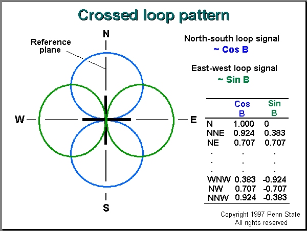
Loop antennas are most sensitive to fields arriving in the plane of the loop, and have minimum sensitivity to fields arriving at 90 degrees to that plane. For vertical loops, which are small compared with the wavelength of received signals, the sensitivity pattern is a function of the cosine of the bearing (direction or azimuth) of the incoming field, as measured with respect to the plane of the loop. Because there is not a unique cosine value of the signal for fields arriving from either side of this plane, a second loop, placed at right angles to the first, derives a second signal to remove this ambiguity. The two loops together constitute the popular crossed loop antenna configuration.
 

If the plane of the first loop is oriented north to south and is considered the reference plane, then the second, east to west, loop derives a signal according to the sine of the incoming bearing. When this value is combined with the cosine of the bearing, fields from any direction have a unique combination of signal 
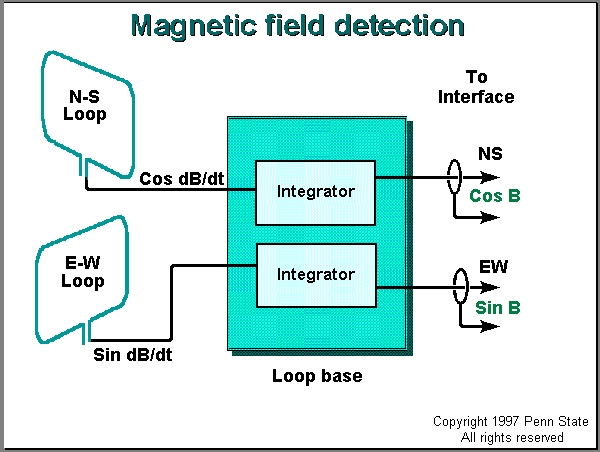
pairs. Because the loop signal voltages are a function of the rate of change of the intercepted magnetic field, integrators are used in the signal pathways to obtain each of the two (NS and EW) signal magnitude components.  These functions are performed in circuits in a box at the base of the antenna array.  Finally, as phase distortions from interactions between the voltage and magnetic components of the intercepted field may occur, the loops must be electrostatically shielded, by forming with coaxial cable, in order to respond only to the magnetic component of the lightning radiation.


The magnetic field component of the antenna array. Integrators in each loop signal path convert the signals, which are proportional to the rate of change of the incoming fields, to signals that are proportional to the two field strength components.
 

The relationship between the incoming magnetic field strength, B, in webers/square meter, and the integrator output voltage V is provided by equation (1) in the original antenna design paper by Krider and Noggle, which is

 
V = [K A cos(q) B] / (R C)        (2)
 
where
V = peak integrator output, in volts
K = net preamplifier gain, dimensionless (about 10 with prototype component values)
A = area of loop (1 square meter in prototype)
cos(q) = cosine of the bearing q of the stroke source [assume cos(q)=1 for signals in the plane of the loop]
B = magnetic field strength in webers / square meter
R = integrator input resistance, in ohms (332 ohms in prototype)
C = integrator feedback capacitance, in farads (0.001 microfarads in prototype)
 
Solving for the prototype values we get:
 
V = (10 x 1 x 1 x B) / (332 x 10^-9) = 3 x 10^7 B, in volts
 
If we use the more convenient practical B' value for the magnetic field, then we get:
 
V = 0.3 B', in volts         (3)
 
For the typical stroke at a range of 100 kilometers whose magnetic field, B', is about 2 webers'/square meter, the prototype integrator output is 2 x 0.3 or 0.6 volts for signals in the plane of the loop. Because the two loop signals are combined, trigonometrically, in the software, the net magnetic field peak signal magnitude is independent of bearing.
 
Note: If a search engine brought you directly to this page, then go to the GP-1 Start Page.
The Web address for the GP-1 Start Page is http://bub2.met.psu.edu/default.htm

Page 6 of 10
Page:1|2|3|4|5|6|7|8|9|10