 |

 |
| Introduction | construction-1 | Construction-2 | Construction-3 |
 |
Construction
This project may be not suitable for the beginners as a certain amount of experience is required to achieve a good operating system , nevertheless the following construction suggestions should help everyone in preventing most problems .
Unless you never make mistakes use sockets for all the IC's.
Keep all leads especially capacitor leads as short as physically possible.
Best operating voltage is a regulated 9 volts DC supply .
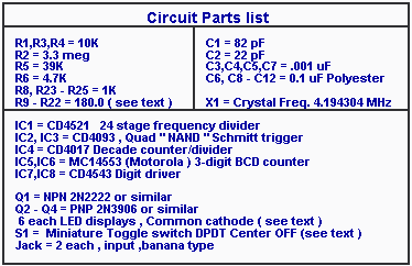
Use two 14 pins IC socket for R9 to R22 for quick adjustments . No need to mess up the PC .
If and external power supply is used AC or DC install a regulator as well as a large filtering capacitor (1000 uF) for stability.
The transistors used can be any general purpose PNP small signal transistors similar to the one listed but pins layout is to be taken in consideration to fit the PCB if used .
The switch S1 is a miniature DP3P with Center OFF . As it is used to apply power to the circuit as well as signal range selection -it must be rated at 120v/3A . See illustrated application with power supply section .
The following will produce noise ; bad capacitors , poor wiring, cold solder , bad connections , noisy supply lines , dirty switch contacts .
LED Displays
The circuit was designed to use Common Cathode LED displays which I already had in my junk box . Any size and colour can be used as long as you can get the right colour filter for their use.
Important Note : For common cathode Pins 6 of the two 14543 ICs ( IC-7 and IC-8 ) must be connected to the negative bus by bridging with a bit of solder to pins 7and 8 of each IC.
Using common anode display
The design can easily be modified for the use of Common Anode LED displays as follows ; ( please refer to the Circuit layout )
1 - Still using PNP transistors , reverse their polarity so that the collector is now connected to digits 1 to 6 , the base connections remain the same as connected to the 1K resistors and the emitter will now be connected to the positive bus by doing the changes described in para 2.
2 - Remove Jumper 1 ( J1 ) and relocate and solder C13 in its place , install a jumper J2 at C13 former position . The transistors emitter are now connected to the positive instead of the negative bus .
3 -Install jumpers J3a and J3b from pin 6 of the 14543 IC's ( IC-7 and IC-8 ) to the positive bus as shown .R9 to R22 are the segments current limiting resistors connected in series from the segment drivers IC-7 and; 8 . A maximum current of 10 ma per segment is recommended for long operating life of the LED displays , a 180 to 200 ohm resistor per segment should be used and can be increased in value as long as the brightness is acceptable thus saving on the current supply source .
To ease the burden of connecting that many resistors I used two 14 pins Dip sockets as shown in the PC layout section and installed two 7 x 181 ohm isolated resistance Dip ( called SIP ,see parts list ) This leaves you the option for easy adjustment of the brightness by substitution if required later depending on the LED displays that you use.
Display
Shown below is a description of multiplexing the six LED digit displays . You will notice that two sets of three displays segments are interconnected and that the six digit common anodes or cathodes are connected in two set of three digits as shown to be controlled by the three digit select transistors .
Example of single ( with jumpers in red ) or double layer PCB for six digits , size .56" common anode , standard pin layout .
Because of the pins arrangement of some digit display it is sometime difficult to do a proper job of interconnecting , for that reason you might be able to locate already multiplexed modules ( Sticks ) of three or four digits that you can use . If three are hard to find four digit modules are readily available for a slightly higher price and can be used by omitting connection to the first and last digit of each module when set end to end therefore using only the six center digits . From this point it is a simple task of interconnecting the common pins as required .
Introduction construction-1 Construction-2 Construction-3
If you have any comments or questions email me at roma60@home.com © Laurier Gendron, Burnaby, B.C., Canada. 1998