"Everything you wanted to know about building
stuff but were afraid to ask."
by
Marshall G. Emm N1FN/VK5FN n1fn@mtechnologies.com
[This series was originally published in "73 Amateur Radio" between November 1997 and February 1998]
Part III
If you've been following along with this series of articles, you will have a brand new, working, VM-110 AC Voltage Monitor(1), ready to install in some sort of enclosure. That's what were going to talk about this month-- installing projects in enclosures and finishing up the project so that you will have a useful, attractive device that you built yourself!
When you have built a few projects it might suddenly dawn on you that the "fun part," the electronic work of soldering components onto circuit boards and getting things to work, is usually less than half of the job! Getting the project installed neatly in a box, with labeling or panel marking that doesn't look like it was done in kindergarten, is a lot of work. It involves different skills, and different tools, and is always going to be time-consuming. But it's worth it, as we shall see when we finish the job.
The first problem is to find an appropriate enclosure, or, as we say in the trade, a box. Aside from the obvious considerations of size and shape, you should also think about whether the box should be plastic, or metal, or plastic with a metal panel.
Oops! Wrong question. Metal or plastic? Your choice will depend on the nature of the project and what you have in the way of tools-- plastic is, of course, much easier to work with. But if you are working with an RF circuit or one which will be used in an RF environment, you will want to use a metal box because of the intrinsic shielding effect. Another factor is whether the enclosure must, should, or could be used as a common ground for the circuitry it is to contain. To give you examples of the two extremes, some circuits have a number of controls which are in effect switches to ground or resistances to ground, and it is quite common to use the control panel as the return path (assuming that the panel itself is grounded, of course). At the opposite extreme, some controls need to be completely isolated from ground (e.g. the air-variable capacitors in many antenna tuners) and a plastic box makes this a lot easier. One last consideration in this regard is whether the circuit board will need to be physically attached in the enclosure, in which case clearance of components and solder tracks from the enclosure is a factor if the enclosure is conductive.
Size and shape are fairly obvious parameters, but it is generally a good idea to get a box that is "one size larger" than the minimum size to contain the project. You may also want to think about how you will use the device when it is finished. If it is an "active" device, such as a keyer, you may want to put it in a box that is much larger than actually required so that a) it will stay in one place on your desk, and b) you can "find" the controls without looking.
A good place to start is to "pre-visualize" your completed project. Famous photographer Ansel Adams is credited with inventing the term to describe the process he used in creating a photograph. Try to picture what the device will look like when it is complete, and how it will be used. Some controls, indicators, connectors, etc. need to be immediately accessible (e.g. on the top or front of the box), while others can be located on the back or sides. In some cases you may want to drill "access holes" for board mounted trimmers. And don't forget the wires! If there will be wires entering the box rather than connected via jacks, then there will have to be holes for them, usually on the side of the box closest that will be closest to where the wire goes, when the unit is in operation..
You should also devote some thought to how the device will be mounted in the box. If it is something like a QRP transceiver that is likely to need adjustment or alignment or modification from time to time, then you want to make it fairly easy to "open it up." A normal box has six surfaces (four sides plus top and bottom) that you can attach things to-- if you use more than two of them you will have a real Chinese box puzzle to take apart! If there are board mounted controls that you will need occasional access to, then be sure to use enough wire when you connect the board to the panel that you can remove the panel and have room to work without having to disconnect wires.
Fortunately, if you have the basic electronic tools described in part one of this series, you have most of what you need to work with enclosures. The most important additional tool is an electric drill (or drill press) and a set of good drills in various sizes. If you are going to do a lot of building, you might want to think about an inexpensive drill press. Sears has one for around the $100 mark. It has other uses around the shop and home, and there is really no substitute when it comes to doing precise drilling. The drills (sometimes called bits) themselves usually come in sets with graduated sizes. You have your choice of SAE, metric, or "numbered" series, but I'd suggest going for a good set of drills in a series with 1/32" increments, which will allow you to match just about any required size, metric or otherwise. A set up to a maximum diameter of 3/8" will cover most requirements, but you might also want to purchase individual drills for 7/16" and 1/2". The larger drills are often available with a 1/4" or 3/8" shaft.
The drills are all you need for the VM-110 project, but here's a list
of tools to round out your collection--
Hacksaw, for cutting the ends off of the shafts of pots and rotary switches.
Hacksaw blade, for use by hand.
Calipers, for measuring drill bits, shaft diameters, and hole diameters.
Files, flat, round, and half round.
Sheet metal nibbling tool, for making odd shaped holes.
Crescent (adjustable) wrench, small, for tightening nuts on pots and switches.
A Box for the VM-110
Having due regard for all of the considerations mentioned above, I chose
the Radio Shack .
#270-230 for the VM-110 project. It's a plastic box with a thin aluminum
panel. An all plastic box would probably be even better, but I couldn't
find one that was just the right size. There is enough room in the box
for comfortable working, and also for a second unit if we decide to add
the VM-12 DC voltage monitor later.
To install the VM-110 in the enclosure, it is necessary only to drill holes for the LEDs, and make some provision for the power cord (from the wall-wart). The circuit board will be mounted to the metal panel simply by gluing the LEDs in place.
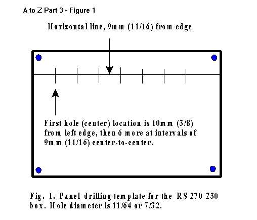
While you could drill a hole near the bottom of the box for the cord (and that is something you will often want to do with more elaborate projects) in this case it is very easy to cut a small notch in the top edge of the box (at the right end as you are looking down on it. That way you can remove the thing from the box without disconnecting the power cord if you need to later. Figure 1 shows the details of the notch.
To make the notch, make the two vertical cuts with your cutters or hacksaw
blade, then bend the "tab" back and forth with a pair of ordinary pliers
until it breaks off.
Once you've chosen your enclosure, the next step is to lay out the panel and do any necessary drilling and fitting.
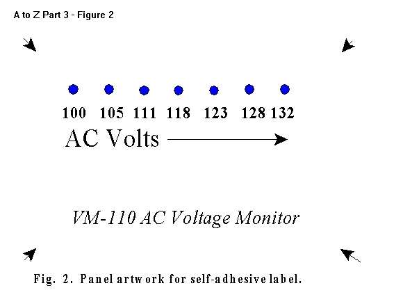
Laying out the panel is simply a matter of marking the locations of holes for the hardware that is to be mounted on it. It seems as if I am always telling you that there are two ways (or more) to do something. Guess what? There are two practical ways to lay out your panel. The first is to physically measure everything and make appropriate marks directly on the panel. The second is to use a template, or a paper representation of the panel that can be attached to the panel and drilled through. The VM-110 is such a simple project that you can easily do it "by hand," but I've provided a template which can be used (Fig. 2) if you are using the specified Radio Shack box.
There are four steps to laying out the panel by hand:
2. Do the measurements and arithmetic. A short (6") flat steel rule (obtainable from most hobby shops and business supply houses is perfect for this. If you must use a tape measure, use an old carpenter's trick and measure from the 1" line rather than from the hook on the end of the thing-- just remember to subtract the 1" from absolute measurements! It helps greatly if you are familiar with the metric system and have a metric rule, because the arithmetic is so much simpler. For example, let's say you have seven holes, 11/16" apart. How far is it between the two end holes, and how far is the first hole from the left edge of the panel? You'll find it's much easier to use 9mm instead of 11/16". You will also note that the actual specifications of many components are metric. Getting down to specifics now, when you measure the LEDs on the VM-110 you will find that they are generally 9mm apart (measuring from the center of one to the center of the next). The leads are slightly flexible, but if you hold the ruler firmly against them you will see that they can all be centered at 9mm. So what we have learned so far is that we are going to need to lay out seven holes in a straight line, with 9mm between the centers. The length of the line will be the total sum of the distances between the holes, or the spacing times the number of holes minus one. In this case, the line from the center of hole 1 to the center of hole 7 will be 54mm long (9mm x 6). The width of the panel is 78mm, so to center the line you would find the "unused" width, namely 78-54=24mm and divide by two to give you the empty space on each side of the line-- 12mm. Or, to put it another way, the first hole will be 12mm from the left side of the panel. Double-check everything, and make sure that the installed components will still fit inside the box if mounted in these positions.
3. Mark the panel. You mark it with a pencil or a pen (depending on what the surface is like) or scratch your marks using an awl or a center punch. For the VM-110 we need to mark the positions for seven LED holes on the panel. Start with a straight line across the width of the panel, 9mm or (11/16") from the top edge. Mark a spot 9mm down from the edge at the left side of the panel, then another spot 9mm down from the edge at the right side, then use a straightedge to draw a line between the two marks, across the panel at a consistent 9mm from the top. Measure 12mm along that line from the left edge of the panel and mark the position for the first hole. Measure and mark the other six holes at 9mm intervals (again, metric makes it easy because you can just add 9 to the last position mentally and read it straight off the ruler). You should now have seven holes, and the rightmost one should be 12mm from the right edge of the panel.
4. Check it all again. Seriously, you haven't done anything yet that can't easily be undone. Go one step further and you risk ruining the panel if you made a mistake! Or as my carpenter father-in-law always says, "measure twice, cut once."
If you have a drilling template for the panel (Figure
2) you can avoid all the hassle of measuring and calculating-- just
attach it to the panel with rubber cement or cellophane tape.
By punching, I mean center-punching the hole locations, not using a punch to create the hole!
Any drill, whether you hold it in your hand or are fortunately enough to own a drill-press, will have a tendency to "wander" if you don't center-punch the material before you drill. A center punch is the correct tool for the job, but you can use an awl or a nail if need be. Place the panel on a block of wood or other hard surface, and carefully place the tip of the punch on the mark for the center of each hole. Tap the end of the punch gently with a hammer or mallet so that the punch leaves a tiny dent in the metal. If you are working with plastic (and sometimes with aluminum), you can get an adequate dent just by pressing firmly on the punch rather than hitting it with a hammer.
Drilling can be tricky, and despite the ready availability of power equipment and high speed twist drills it is worth going over the basics. As with most tools, you develop skill as you go and if you are experienced at drilling holes in things you will have no trouble with this sort of work. On the other hand, if you have never used a drill before, you will find it is tricky at first but gets easier with practice.
Use a backing block! Clamp the panel firmly to a block of wood and drill through the panel into the wood. This will reduce (if not eliminate) burring on the bottom side of the panel, and reduce the likelihood of the panel slipping. You will be tempted sometimes to hold the material by hand, but you will learn over time when it is safe to do that and when it is likely you will end up with a sprained or broken finger, or worse. Eye protection is also a must.
Once the holes are drilled, you will need to remove the "burring" on the bottom side of the panel. You can do this with a file, a "rosette" countersinking bit, or even your hobby knife as long as you are working with aluminum or plastic. Another technique is to use just the tip of a slightly larger drill bit (which is what you will probably have to do with a steel panel).
Check it all again. In this case, if you made a terrible mistake of some kind you can start over and re-drill the holes on the other side of the panel-- the suggested panel label will cover the unused holes, or you can cover them with a piece of masking tape if you are labeling your panel that way.
Hole too small?
That's not going to be a problem with this project, but since it is such a common problem I'll give you a couple of pointers. The techniques vary quite a bit depending on the material you are working with as well as the size and shape of the hole and, of course, the tools available to you.
Let's say you need to mount an SO-239 coax connector, which has a hole about 5/8" in diameter and the largest drill you have is 3/8." The "correct" solution is a chassis punch, but who can afford those? I'm still kicking myself for leaving a cheap set (about $20, including 5 punches for common sizes up to 1-1/2 inch) behind in Australia-- nobody seems to sell anything like that now.
So you'll have to make do. Drill the hole to 3/8" and then use a pencil
or scribe to trace around the connector so you can see how large the finished
hole must be. Then use one of the following techniques to enlarge it.
Good-- A round file. A good choice is one of the round files used for sharpening chainsaws, because they are readily available and relatively inexpensive. Just file the hole out to the line that you marked, checking the fit periodically.
Better-- A half-round file. A half-round file (rounded on one side, flat on the other) is much easier to use with larger holes because the curve is more gentle and it is easier to control.
Alternative-- A small grinding cylinder on a drill press or "Moto- tool "hand-held device. You can also use a small sanding drum if you are working with aluminum or plastic. I've been known to chuck a round file in the drill press, but this is not recommended for reasons of safety.
Holes with Corners?
No problem. This seems to be a real challenge for a lot of builders, but producing a rectangular hole is just a matter of patience and the right technique.
If the hole is large enough, an inexpensive sheet metal "nibbling" tool will get the job done in no time. The nibbler takes a tiny, rectangular bite out of sheet metal and it's simply a matter of nibbling your way around the opening. Leave a bit of an edge, though, because the finish is not very smooth and you will want to "dress" the opening with a file.
Another option is to drill a line of very small holes around the opening, then use a hacksaw blade to cut between them, finally cleaning up the line with a file. Drill one larger hole at a corner of the opening so you will have a place to insert the hacksaw blade. You might want to wrap some duct tape around the end of the blade that you will be holding, otherwise it's pretty hard on your hands. For a fairly large opening you might even want to insert the blade through the hole and then reinstall the hacksaw frame. If you have a scroll saw or a saber saw you can get hacksaw blades for them, too.
Putting it all together
Now it's time to install the circuit board in the enclosure. Or is it? If you are going to use an adhesive label for the panel, you need to apply it to the panel before you install the board, so skip ahead to "Making it Pretty" and come back to this section when you have your label finished.
The seven LEDs on the VM-110 should fit neatly into the seven holes you drilled in the panel. Hold the board straight (so that it is parallel to the panel) and secure the LEDs by applying a good all-purpose cement or hot glue on the inside of the panel. Use a liberal amount, because that's all that's going to hold it together. And that's it. Now guide the cord into the little notch you made, slap the lid on and screw it down.
It's a good idea to put a knot in the cord on the inside of the enclosure near the hole where it enters. Then if someone pulls on the cord or it gets caught on something, the knot will take the strain and prevent the connections to the circuit board from coming loose. For two-conductor cords like that used in the VM-110, a simple "electrician's knot" will suffice. Split the two conductors over a distance of about 2" from the end and tie half of a square knot. This is one of those cases where a picture is worth a thousand words, so I've attempted to draw it for you (figure 3). Obviously the end of the cord must be free, i.e. not connected to the circuit board. If you'd rather not disconnect it, you can tie a simple overhand knot.
Commercial kits often come with a box that has been silk-screen printed or which has a printed decal to show the manufaturer's logo and necessary control indications. But that is a hugely expensive process that is impossible to justify for run-of-the-mill kits, especially if you only need one.
We've come a long way in readily accessible labeling technology in recent years. I've built things on wooden "breadboards" and made pencil marks on the wood. I've used masking tape with pen and ink markings, and I've used indelible pencils to write directly on panels. And I confess I have a large number of "devices" with no markings at all! Then there are the Dymo labels-- I remember when they were really cool (and expensive); now they are inexpensive, but they look pretty tacky.
An attractive, inexpensive, and reasonably simple approach is available now if you have a computer graphics program and a good printer (say, 300 dpi resolution, whether dot matrix, ink jet, or laser). The computer program lets you design a very attractive label for your panel, and the printer will produce the label on self-adhesive material which you can easily apply to the panel. If your "working conditions" don't include an adequate computer, program, or printer, you may be able to use one at your local Kinko's or even a public library.
As usual, I'm going to give you the specifics of how I prepared the front panel artwork for the VM-110 project, but the principles can easily be adapted I'll try to explore a number of options. But first I'll give you the summary on how I do most of my small project lables--
Print the label on whole-sheet label stock (Avery # 5265 or #8165). Sometimes you can also use a copy of the finished artwork, printed on plain paper, as a drilling template.
Apply the label to the panel.
Apply an "over-coat" of clear self-adhesive vinyl, e.g. "Kittrich Magic Cover book-cover material, available from most drug stores and stationers..
Clear the material from the holes and mount the controls.
An obvious option, which I have seen done to good effect, is to paint the panel, then apply a label printed on transparent label stock.
The computer program needs to be capable of drawing with a fairly high degree of accuracy in literal scale (that is, if it says it's an inch on the screen it should print out as an inch). I use WordPerfect version 7, which incorporates a cut-down version of Corel Draw that is adequate for most purposes.
Most drawing programs have a quick means of drawing squares and rectangles, so I usually start by drawing an outline of the panel, just to provide visual reference points and measurements from edges (I delete the outline before printing). Use small circles or dots to indicate the position of holes for controls and mounting screws-- these will help you line up the label when you apply it to the panel. Remember to leave clearance for knobs for pots and such! It's extremely frustrating to go to a lot of trouble to produce a panel label and then discover that when you put the knobs on the shafts, you've covered up your text.
Print the label on plain paper first, and hold it (and the panel) up to a strong light so you can see that everything lines up. Once you have it right, print it on the label stock. I usually print out two copies, just in case!
Indexing the label to the panel is not difficult. I usually hold the panel and label up to the light and use a pencil to mark the position of a couple of holes. Then on a cutting board I put the panel on the label, matching the pencil marks, and trim around the panel with a hobby knife. I repeat that process with the clear vinyl, then use the hobby knife to trim out the label material from the holes.
The first time I prepared a project label this way it seemed like an awful lot of work, but the results were certainly worth it. As time goes by it gets a lot easier.
But What if It Doesn't Work?
If you go outside late at night, most any night, and listen closely, you can faintly hear the pathetic sound of kit builders all over the world crying because they just can't get it to work. There are screams of rage, too, and crashes as non-functioning kits hit the wall or are reduced to atoms on the anvil. You can smile though, because you are outside getting a breath of fresh air while you think about what to build next. We hope. But even in the best of families, things occasionally will go long and Murphy is always lurking. If your project doesn't work, 97 times out of a hundred(2) it will be because you did something wrong. One time in a hundred it will be due to a faulty component, and one time in a hundred it will be due to a mistake in the instructions. Finding the problem can be time-consuming and frustrating, but it doesn't have to be. All you need is a plan, and we'll see if we can come up with one next month.
1. Rainbow Kit VM-110, $10.95 (+$5 s/h) available from Milestone Technologies Inc., 2460 S. Moline Way, Aurora, CO 80014, or call 800-238-8205 for credit card orders. Also available from Electronic Rainbow Inc., 6227 Coffman Rd., Indianapolis, IN 46268 or call 317-291-7262.
2. Numbers are based on independent research audited
and verified by Dewey, Fixem, & Howe.