"Everything you wanted to know about building
stuff but were afraid to ask."
by
Marshall G. Emm N1FN/VK5FN n1fn@mtechnologies.com
[This series was originally published in "73 Amateur
Radio" between November 1997 and February 1998]
Part I
As the doctor said to the patient, "I've got good news and bad news." The bad news is all around us-- increasing prices, decreasing skills base, no more Heathkits... and if you want more, just pick up a newspaper. The good news is that you can still build a lot of useful ham radio equipment and you don't have to be an electrical engineer to do it. All it takes is the right tools, knowledge of a few "tricks of the trade," and the will to succeed. Oh yeah-- a bit of patience helps too! We're going to try to cover the whole topic here in enough detail for you to pick up a soldering iron and get to work on a real project. First we'll talk about the basics, things like tool selection and soldering, then we'll move on to middle-to-advanced techniques, and finally trouble-shooting the finished project and installing it in an enclosure. Along the way we'll build something useful, I promise. You're going to discover that building is rewarding, educational, and fun!
Before we start, let's look at a fairly obvious question-- why build something when you can buy it? There are several reasons for building (even if you only need one)--
A Disclaimer, of Sorts
I'm in the business. My company, Milestone Technologies, sells some of the tools that I am going to recommend and also the kit that we're going to do as a project. I'd hate to think that you would think I'm writing this series to sell stuff, so I will make a point of providing an alternate source for each of those items that I sell. Making some of these things available to you from Milestone Technologies is a service which you are free to decline.
A Poor Workman Blames his Tools
A crummy violinist playing a Stradivarius is going to sound like someone scraping a horse's tail across a cat's gut. A great violinist can make a cigar-box violin sound like a Strad. Or to put it in more familiar terms, an unskilled ham will have trouble making contacts with a three thousand dollar rig and a beam on a 100' tower, while a skilled operator can work DXCC on a home-made QRP rig with a dipole. The point here is that skill is more important than tools-- investing hundreds of dollars in tools and test equipment is not going to make you a good builder or technician. The value of your tool armory will increase as time goes by, but the basic tools for electronic construction are relatively inexpensive, and all of them are available at your local radio parts store and by mail-order.
Let's talk about a two basic tool kits for electronic construction-- hand tools and soldering tools.
The hand tools are really simple at "entry level" but even basic soldering tools start to get into areas of complexity, so you may want to read the section on soldering before deciding what to buy. The recommendations are summarized in table 1, which shows suppliers part numbers for Radio Shack (RS)(1) and Milestone Technologies (MT)(2).
Hand tools:
Screwdrivers-- you will need two large screwdrivers, one with a straight tip for slotted screws, the other with a phillips head; and a set of miniature drivers. The mini drivers (often called "jeweler's drivers") can be bought as separate sets for straight and phillips, or as a combination set.
Hobby knife-- for example, a "Stanley" knife, with a razor-sharp blade, for stripping wires and trimming things.
Multimeter-- for checking voltages, resistances, continuity, and current. A digital multimeter with an "audible continuity feature" is great, but you can get by with an inexpensive VOM (Volt-Ohm-Milliameter).
Magnifier-- for examining circuit board traces and solder connections. If you can, you should solder under magnification using a magnifying work lamp, but you can start with a hand magnifier or loupe.
Clip leads-- wires with aligator clips on the ends for making temporary connections.
Sheet Metal Nibbling Tool-- for making large or odd shaped openings
in sheet metal, for example aluminum panels for mounting controls. Much
faster and easier than filing.
Solder wick-- you will make mistakes. I do, and everyone does. Besides, there will be times when you want to remove a component for testing, or to substitute a different value. The only practical way to "unsolder" a connection is with solder wick. You'll see solder suckers and other "one hand" desoldering devices, but if they are any use it all it is because you used way too much solder on the connection to start with!
When it comes to light, you simply can't have too much. Flourescent light is best for electronic work because it is "whiter" than incandescent light. Ventilation is particularly important when you are soldering, because the fumes from the rosin can be irritating or even harmful over time. You will need mains power for your soldering iron, and you will often need to connect things to a good electrical ground (the center screw in the AC outlet will do).
Other than that, all you need to worry about is a reasonable amount of clear space, and places for tools and components. If you are using a space that has other purposes (i.e. your kitchen table) it's easy enough to keep your tools and components in trays so they can be easily put aside when you are not working.
Entire magazine articles, even books, have been written about soldering. So how can I hope to teach you to solder with a few paragraphs and illustrations? Easy. Soldering is not difficult, and the basics are easily within your grasp if you have the right soldering iron, the right solder, and a little bit of practice.
Practice is important, so if you are new to soldering please take the time to do some before we start on the project! You can practice on any old components and a bit of scrap circuit board material-- or skip ahead to un-soldering, remove a couple of components from a junk circuit board and re-solder them. Kit suppliers will tell you that 90% of all problems in kit building are a result of poor soldering-- how can that be if soldering is not difficult? Simple-- carelessness and ignorance. We'll fix the ignorance problem right now-- carelessness is up to you.
Soldering is a process of amalgamating metals to provide a good electrical
connection.
Solder is a mixture (alloy) of two or more metals with a relatively
low melting point, that will flow onto the surface of other metals creating
a low-resistance electrical connection. Ordinary solder is not very strong,
and you should never rely on solder alone to hold components together physically.
| Rule #1: A good mechanical
connection
is
necessary before you solder! |
The purpose of the soldering iron is to transfer heat into the work to be soldered; the solder should melt upon contact with the work. The iron must be at the correct temperature to do this, and some elementary principles of thermodynamics are involved here.
| Rule #2: Strike while the iron is hot! |
The wattage of an iron is a measure of the power that is used to generate heat. Your soldering pencil is always running at that level of power consumption, and it is always generating heat. The tip has a specific mass which can absorb heat. As long as power is supplied it will continue to get hotter until it reaches equilibrium-- at its maximum temperature heat will be conducted away from it (into the surrounding air) as quickly as it is generated by the applied power. Heat will transfer out of the tip more quickly when it is in contact with the work, and the rate at which that occurs will depend on the size and shape of the tip, the amount of its surface that is in contact with the work, and the nature of the work (how quickly heat is conducted away from the point of contact). When your soldering pencil is sitting idle it very definitely gets much hotter than required for soldering, but it cools down almost instantaneously when you apply it to the work, and the applied power sustains the working temperature. When it's idle though, at higher temperatures, its surface is much more susceptible to corrosion. So turn it off when you are not actually soldering (for more than five minutes or so). Otherwise, you can expect to replace or refinish the tip fairly frequently. Leaving it on overnight once will ruin the tip. Once the tip has been overheated and cannot be tinned (see below) you can file or grind it down and start over, but it is usually a lot easier just to replace it.
All else being equal, the wattage of an iron is a poor indicator of its performance because it's main effect is in how quickly the iron will heat up to its maximum equilibrium temperature, or how fast it will create new heat for transfer into the work, and not necessarily how hot that temperature will be! That's why the best irons, if somewhat more expensive, are temperature controlled and not "variable output." I finally worked that out for my self after going through perhaps a hundred soldering iron tips.
From this point on, I'll be talking about soldering components onto a printed circuit board, but the principles apply to other soldering such as wire connections to controls.
Allow the iron to heat until solder flows freely on the tip, "tinning it." This means there should be a thin, shiny coating of solder on the working surface of the tip-- it should not "ball up" and drop off. Apply a small amount of solder to the tip and then wipe it off quickly with a soft cloth or a damp sponge. You can probably do three or four joints in immediate succession without having to repeat this process, but if you stop soldering to place components on the board you will need to repeat it.
Here are the steps in soldering a component into a circuit board:
2. Mechanically install the component. Use your long-nose pliers to bend the component's leads so that they will go straight into the holes in the board. If the spacing permits, hold the lead with the pliers and bend the end of the lead against the jaws of the pliers. Otherwise, watch what you are doing and make sure you are not exerting excessive pulling force on the lead-- you can easily ruin a diode or inductor by pulling on the lead. Check the value before you insert it in the board. If it is a polarized component such as an electrolytic capacitor, double check the orientation. If the component isn't polarized (for example a resistor or ceramic capacitor) then it doesn't matter which way it goes, but it's a good idea to mount it so that you will be able to read the value later. I usually put resistors in with the tolerance band to the right or bottom depending on how the resistor is mounted, and capacitors with the value facing me or to the right (unless they are very close to a larger component, in which case I turn them around). The aim is simply to make it easy to see and verify all of the component values after the board is complete. Before you solder it, RECHECK the value, the orientation, and that it is in the right holes! In most cases, the body of the component should be snug against the component side (opposite from the "track" or soldering side) of the boards. Obvious exceptions are transistors and other components which might run hot. Looking at the solder side of the board, bend the leads outward at about 45 degrees to hold the component in place.
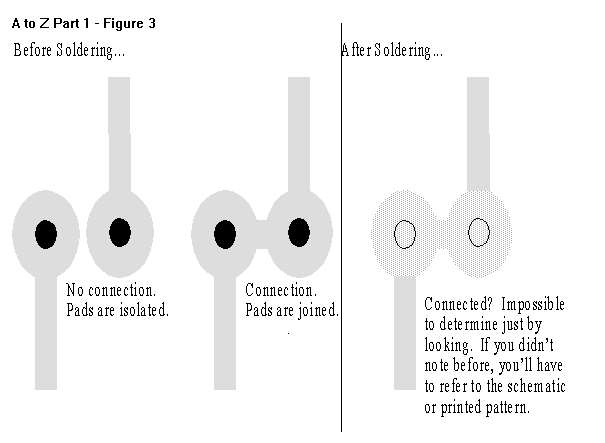
3. Inspect the un-soldered connection. Make sure you know where solder is supposed to go. For example, if there is a pad for another component very close to where you are going to solder, you can "memorize" the pad layout and be sure that there is no unwanted solder "bridge" when you finish the connection. If you don't do this, it's often hard to tell whether two points should be connected or not. Examine figure 3 for an illustration of this.
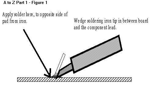
4. Solder the connection. Tin and wipe the tip of the iron as described above. Apply the tip to one side of the pad, wedging the tip against the lead where it protrudes from the hole, as shown in figure 1. Count to three and apply solder to the opposite side of the pad, and it should flow across the pad, around the lead, and slightly up the lead from the surface of the board. Do NOT apply the solder to the tip of the iron, as it will melt instantly and may flow onto the joint without bonding properly.
| Rule #3: Heat the work, not the solder! |
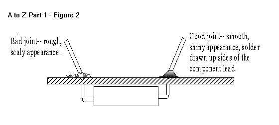
5. Inspect the soldered connection. Use a magnifying device of some kind, ideally 5-10x power and make sure the connection is sound and conforms to the illustration in figure 2.
| Rule #4: Inspect the connection under magnification! |
6. Trim the component leads. Use your flush cutting pliers and trim at about the point where the solder has risen up the lead. It is not usually necessary, or even a good idea, to trim the leads of integrated circuits and other devices where the lead protrude only an eighth of an inch or so.
When you've soldered all the components onto the board, check everything
again-- component values, orientations, and above all look for solder
bridges and cold joints! When it comes to the latter two, it may be a good
idea to remove excess solder flux from the board, but don't bother with
that unless you really need to-- in my experience more problems are caused
in the process of removing flux than are solved by it. If you do need to
remove flux, use acetone or a commercial flux remover, in a well ventilated
area. If you have invested solder with a water soluble flux, you will
use water, of course, but do make sure the board is thoroughly dry before
applying power to it!
For the most part, anything you can do with solder you can undo, if
you know what you're doing. The secret is "solder wick," a fine copper
braid impregnated with flux. Used properly, it can remove virtually all
of the solder from a connection and a component, even an integrated circuit
chip, will just fall out. A lot of people seem to have difficulty with
it though-- it's one of those things where it's hard to figure out how
to use it by yourself. One big problem is that solder wick should be marked
with a "use by" date! The braid itself can oxidize over time, and the flux
can dry out and fall out of the mesh, making it practically useless. So
use fresh solder wick, and do it like this.
2. Lay the end of the wick on top of the connection that is to be desoldered, and press the iron firmly into the wick. Hold in place (you'll want to hold the wick by its container, or at least six inches from the end) and watch for solder to appear in the wick. When solder is has been drawn about half an inch from the end of the wick remove the iron and the wick.
3. Cut the used end of the wick off, about a quarter inch above the point at which solder is visible. Solder has not been drawn up that far, but the flux has boiled out.
4. Repeat steps 2 and three until the component is free. It will usually take two or more applications for each lead. Keep in mind that where circuit board holes are plated through, solder has flowed down from the track side of the board and as a result there will be more solder to remove than on a simple single-sided board.
If you have trouble, remember that the two secrets are fresh
solder wick, and plenty of heat!
To repair (remove) a solder bridge, apply the wick to the bridge and the solder should be removed from the board between the two pads-- you may need to resolder the connections, though.
Next month we'll build our project-- in the mean time you can get your tool kit together, practice soldering, and order a kit. It's the VM-110 AC Voltage Monitor from Electronic Rainbow , and if you don't want to order the kit you can find most of the parts pretty easily-- a list will be printed next month along with the schematic. The VM-110 kit costs $10.95 and you can order the complete kit or just the circuit board from Electronic Rainbow(3), or the complete kit from Milestone Technologies.
|
|
|||
| Item | Supplier | Price | Part Number |
| Long Nose Pliers | RS | 3.99 | 64-1844 |
| Cutting Pliers | RS | 3.99 | 64-1833 |
| Screwdriver, reversible | RS | 2.69 | 64-1950 |
| Jeweler's driver combo set | RS | 4.79 | 64-1959 |
| Hobby Knife | RS | 1.49 | 64-1805 |
| Magnifying Glass | RS | 5.99 | 63-848 |
| OR Jeweler's Loupes Set(3) | MT | 7.95 | 35450 |
| Multimeter, 8-Range Analog | RS | 14.99 | 22-218 |
| OR Multimeter, 14-Range Analog | MT | 9.95 | 30812 |
| Clip Lead Set (10) mini aligator | RS | 3.99 | 278-1156 |
| Sheet-metal Nibbling Tools | RS | 10.99 | 64-823 |
| OR Heavy Duty Nibbling Tool | MT | 9.95 | 00539 |
|
|
|||
| 15-Watt Soldering Iron | RS | 7.99 | 64-2051 |
| Replacement Tip for Above | RS | 0.99 | 64-2052 |
| Solder, 60/40 rosin core .032" 2.5oz | RS | 3.79 | 64-005 |
| Desoldering Braid | RS | 2.29 | 64-2090 |
1. Radio Shack-- call (800) 843-7422 for location of nearest store, or to order by phone.
2. Milestone Technologies, 2460 S. Moline Way, Aurora, CO 80014 (303) 752-3382, orders (800)238-8205 email: sales@mtechnologies.com, http://www.mtechnologies.com/mthome
3. Electronic Rainbow Inc., 6227 Coffman Rd., Indianapolis, IN 46268 (317)291-7269.
4. Prices were current published retail at time of preparation but subject to change