Home Page

Handy Dandy Little Circuits #17-3

FM Receiver

You could use a small FM receiver for convenience taking the output signal from the headphone connector connected to an external volume control ( about 10K ohms ) then to the decoder.

If you have something smaller in mind then the following FM receiver can be constructed with the TDA7000 IC which is still available from some distributors . No special skill is required except care must be taken that all the capacitors all wired as close as possible to the pins. The recommended supply voltage is 4.5 volts but up to 9 volts can be used .

The coil (L1) is made of 6 turns of # 20 insulated wire on a 1/4 " form . Tuning is simple enough once you have your transmitter operating simply tune the variable capacitor with a non-metallic screw driver very slowly until the signal is detected anywhere on the FM band .

The signal output is very small , only suitable for crystal headphone and must be amplified if you want to hear it . The LM386 amplifier is well suited for that purpose . See LM386

            
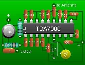
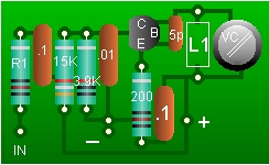
Parts list
C1 = .15 uF
C2 = .002 uF
C3 = .022 uF
C4 , C5 = .01 uF
C6 = 180 pF
C7 , C9 = .003 uF
C8 , C14 = 330 pF
C10 = 150 pF
C11 = 100 pF
C12 , C15 = 220 pF
C13 = .1 uF
C16 = 47 uF /15v
C17 = 10 -20 pF Var.
R1 = 10K
R2 = 22K
L1 = see text
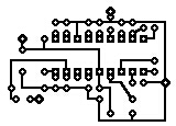
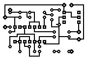
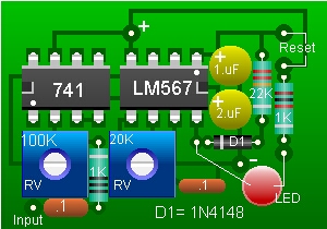
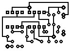
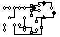
Layouts and PCBs

The following shows PC layouts for each circuits on page one and two. For clarity the PCB layouts are illustrated about twice the size than the actual PC board would be. On a standard perforated board , point to point wiring using #24 size wire or smaller can be used with the same layout instead of a printed circuit board .

Detecting Module

Decoder Module

FM Transmitter Module

Back to Page #1

Back to Page #2

Home

If you have any comments or questions email me at roma60@home.com

© Laurier Gendron, Burnaby, B.C., Canada. 1998