
|
#17-2 |
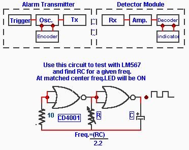
On page one I detailed the Alarm Transmitter functions and said that it could be combined with an Encoder so that the encoded received signal could be decoded for Alarm identification. The following function block shows how it is combined to form a complete system.
 To ease the burden of testing and finding the resistance values to use for each frequency I include a small oscillator to feed the decoder (LM567) , use a 9 volts supply or battery for both units while testing.
Some points to observe 1- Keep R between 2K and 20K After assembly of the test oscillator and decoder select the lowest frequency you want to use and calculate R/C for the values to be used for the decoder and install C . Next calculate R/C for the oscillator for the exact same frequency but use a variable resistor for R within the found values and install . Thereafter you may use the fixed capacitor values for the oscillator and decoder within the frequencies limit you want to use.
Next with a scope or a frequency counter check that the oscillator is working and adjust R to obtain the frequency you want . Turn power off and measure the resitance of R and make note of it with the freq . Do not readjust R . Connect the oscillator to the decoder input, turn the feed-back gain resistor R1 (100K) of the op-amp to one third , turn power on , if you have a scope check for a signal (square wave) at the op-amp output and adjust amplification for a good signal ( ~ 5vdc) then slowly vary the detector resistance R while observing that the LED turns on , STOP right there and measure the detector R and make note of the resistance value at the time the LED is turned on.
Next ,assuming you already have built your first alarm transmitter module and it is working apply the same values of R/C with the closest standard fixed value for "R" as found for the test oscillator to the alarm oscillator. Disconnect the test oscillator from the detector and with a common power supply to the alarm module and the detector use a jumper from the alarm oscillator output and connect to the decoder input and fire up the circuits. If the LED does not turn on readjust first R1 then the detector R until it does and lock in place with a dab of silicon .
P.S. The frequency for the above decoder with values of R = 10K and C = .1uf is 110Hz.
|
© Laurier Gendron, Burnaby, B.C., Canada. 1998