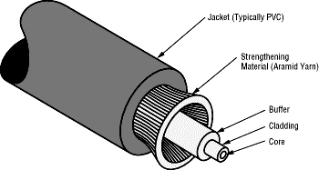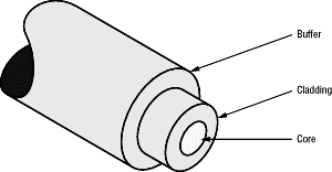
The concentric layers of an optical fiber include
the light-carrying core, the cladding and the protective buffer.
Title: Introduction to Fiber Optic Networking - Contents
Author: AMP, Inc.
Company: AMP, Inc.

Total Internal Reflection
Light injected into the core and striking the core-to-cladding interface at an angle greater than the critical angle will be reflected back into the core. Since angles of incidence and reflection are equal, the light ray continues to zig-zag down the length of the fiber. The light is trapped within the core. Light striking the interface at less than the critical angle passes into the cladding and is lost.

Rays of light do not travel randomly. They are channeled into modes, which are possible paths for a light ray traveling down the fiber. A fiber can support as few as one mode and as many as tens of thousands of modes. While we are normally not interested in modes per se, the number of modes in a fiber is significant because it helps determine the fiberOs bandwidth. More modes typically mean lower bandwidth. The reason is dispersion.
As a pulse of light travels through the fiber, it spreads out in time. While there are several reasons for such dispersion, two are of principal concern. The first is modal dispersion, which is caused by different path lengths followed by light rays as they bounce down the fiber. Some rays follow a more direct route than others. The second type of dispersion is material dispersion: different wavelengths of light travel at different speeds. By limiting the number of wavelengths of light, you limit the material dispersion.
Dispersion limits the bandwidth of the fiber. At high data rates, dispersion will allow pulses to overlap so that the receiver can no longer distinguish where one pulse begins and another ends.
Types of Fibers: Singlemode or Multimode?
In the simplest optical fiber, the relatively large core has uniform optical properties. Termed a step-index multimode fiber, this fiber supports thousands of modes and offers the highest dispersion - and hence the lowest bandwidth.
By varying the optical properties of the core, the graded-index multimode fiber reduces dispersion and increases bandwidth. Grading makes light following longer paths travel slightly faster than light following a shorter path. Put another way, light traveling straight down the core without reflecting travels slowest. The net result is that the light does not spread out nearly as much. Nearly all multimode fibers used in networking and data communications have a graded index.
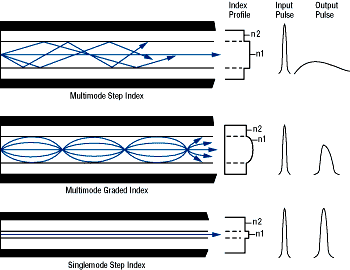
But the ultimate in high-bandwidth, low-loss performance is singlemode fiber. Here the core is so small that only a single mode of light is supported. The bandwidth of a singlemode fiber far surpasses the capabilities of today's network electronics. Indeed, the information-carrying capacity of the fiber is essentially infinite. Not only can the fiber support speeds of tens of gigabits per second, it can carry many gigabit channels simultaneously. This is done by having each channel carried by a different wavelength of light. The wavelengths do not interfere with one another. Singlemode fiber is the preferred medium for long distance telecommunications. It finds use in networks for interbuilding runs and will eventually become popular for high-speed backbones. Applications for singlemode fiber to the desk are not anticipated.
The most popular fiber for networking is the 62.5/125 multimode fiber. The numbers mean that the core diameter is 62.5 micrometer and the cladding is 125 micrometer. Other common sizes recognized by building-cabling standards include 50/125, 100/140, and 200/230 micrometer, although these are declining in use.
Fiber Properties
Numerical aperture (NA) of the fiber defines which light will be propagated and which will not. NA defines the light-gathering ability of the fiber. Imagine a cone coming from the core. Light entering the core from within this cone will be propagated by total internal reflection. Light entering from outside the cone will not be propagated.
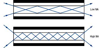
NA has an important consequence. A large NA makes it easier to inject more light into a fiber, while a small NA tends to give the fiber a higher bandwidth. A large NA allows greater modal dispersion by allowing more modes in which light can travel. A smaller NA reduces dispersion by limiting the number of modes.
Bandwidth. Fiber bandwidth is given in MHz-km. A product of frequency and distance, bandwidth scales with distance: if you half the distance, you double the frequency. If you double the distance, you half the frequency. What does this mean in premises cabling? For a 100-meter run (as allowed for twisted pair cable), the bandwidth for 62.5/125-micrometer fiber is 1600 MHz at 850 nm and 5000 MHz at 1300 nm. For the 2-km spans allowed for most fiber networks, bandwidth is 80 MHz at 850 nm and 250 MHz at 1300 nm. With singlemode fibers, the bandwidth for a 100-meter run is about 888 GHz.
        Attenuation (dB/km)  Bandwidth (MHz-km)  NA
           850 nm  1300 nm    850 nm   1300 nm
Singlemode   -       1.0       -       See note  .1
50/125      3.5      2.0      400       400      .20
62.5/125    3.5      1.5      160       500      .275
100/140     5.0      4.0      100       200      .29
Note: The bandwidth of a singlemode fiber is essentially infinite in that it surpasses the ability of today's electronics to exploit its capabilities.
Attenuation. Attenuation is loss of power. During transit, light pulses lose some of their energy. Attenuation for a fiber is specified in decibels per kilometer (dB/km). For commercially available fibers, attenuation ranges from approximately 0.5 dB/km for singlemode fibers to 1000 dB/km for large-core plastic fibers.
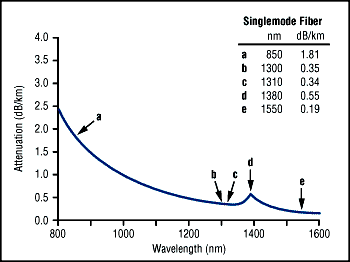

Attenuation varies with the wavelength of light. There are three low-loss "windows" of interest: 850 nm, 1300 nm, and 1550 nm. The 850-nm window is perhaps the most widely used because 850-nm devices are inexpensive. The 1300-nm window offers lower loss, but at a modest increase in cost for LEDs. The 1550-nm window today is mainly of interest to long-distance telecommunications applications.
Cables
The fiber, of course, must be cabled - enclosed within a protective structure. This usually includes strength members and an outer jacket. The most common strength member is Kevlar aramid yarn, which adds mechanical strength. During and after installation, strength members provide crush resistance and handle the tensile stresses applied to the cable so that the fiber is not damaged. Steel and fiberglass rods are also used as strength members in multifiber bundles.
The jacket protects against abrasion, oil, solvents, and other contaminates. The jacket usually defines the cable's duty and flammability rating. Heavy-duty cables have thicker, tougher jackets than light-duty cables. Equally important in a building is the cable's flammability rating. The NEC (National Electrical Code) establishes flame ratings for cables, while Underwriter's Laboratories has developed procedures for testing cables. The NEC requires that all cables run through plenums (the air-handling space between walls, under floors, and above drop ceilings), must either be run in fireproof conduits, or be constructed of low-smoke and fire-retardant materials. For building use, there are three categories of cables:
Riser cables can be used in vertical passages connecting one floor to another. These cables are termed OFNR (optical fiber nonconductive riser).
General-use cables cannot be used in riser or plenum applications without fireproof conduits. These cables are rated OFN (optical fiber nonconductive). OFN cables can be used in offices space - to connect from a wall jack to a computer, for example.
