- Preview
- Products
- Catalog
- Receiver Protectors
- Magnetrons
- TWT's
- CFA's
- Transmitters
- Switches
- Pressure Windows
| Magnetrons |  |
|
Theory of Operation
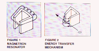
A magnetron is a high power microwave oscillator in which the potential energy of an electron cloud near the cathode is converted into r.f. energy in a series of cavity resonators similar to the one shown in Figure 1. As depicted by the low frequency analog, the rear wall of the structure may be considered the inductive portion, and the vane tip region the capacitor portion of the equivalent resonant circuit. The resonant frequency of a microwave cavity is thereby determined by the physical dimension of the resonator together with the reactive effect of any perturbations to the inductive or capacitive portion of the equivalent circuit. This is an important point and will be recalled later.
Magnetron Energy Transfer
Resonator Mechanism
In order to sustain oscillations in a resonant circuit, it is necessary to continuously input energy in the correct phase. Referring to Figure 2, if the instantaneous r.f. field, due to steady state oscillations in the resonator, is in the direction shown, and, an electron with velocity was to travel through the r.f. field such that the r.f. field retarded the electron velocity by an amount, the decrease in electron energy will be exactly offset by an increase in the r.f. field strength.
In a magnetron, the source of electrons is a heated cathode located on the axis of an anode structure containing a number of microwave resonators. See Figure 3.
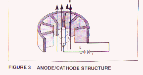 Electrons leave the cathode and are accelerated toward the anode, due to the dc field established by the voltage source E. The presence of a strong magnetic field B in the region between cathode and anode produces a force on each electron which is mutually perpendicular to the dc field and the electron velocity vectors, thereby causing the electrons to spiral away from the cathode in paths of varying curvature, depending upon the initial electron velocity at the time it leaves the cathode.
As this cloud of electrons approaches the anode, it falls under the influence of the r.f. fields at the vane tips, and electrons will either be retarded in velocity, if they happen to face an opposing r.f. field, or accelerated if they are in the vicinity of an aiding r.f. field. Since the force on an electron due to the magnetic field B is proportional to the electron velocity through the field, the retarded velocity electrons will experience less "curling force" and will therefore drift toward the anode, while the accelerated velocity electrons will curl back away from the anode.
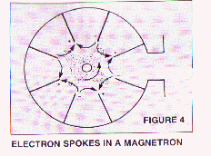 The result is an automatic collection of electron "spokes" as the cloud nears the anode (see Figure 4), with each spoke located at a resonator having an opposing r.f. field.On the next half cycle of r.f. oscillation, the r.f. field pattern will have reversed polarity and the spoke pattern will rotate to maintain its presence in an opposing field.
The "automatic" synchronism between the electron spoke pattern and the r.f. field polarity in a crossed field device allows a magnetron to maintain relatively stable operation over a wide range of applied input parameters. For example, a magnetron designed for an output power of 200 kw peak will operate quite well at 100 kw peak output by simply reducing the modulator drive level.
You will note that the instantaneous r.f. field pattern, shown in Figure 4, has exactly 180o of phase change (radians) between every adjacent pair of resonator vanes and is therefore called the mode. Other oscillation patterns (modes) could be supported by the anode structure; however, the mode pattern will product the maximum number of electron spokes, and therefore the maximum transfer of energy to the r.f. field, i.e., highest efficiency mode. Assuring that the magnetron maintains mode oscillation, to the exclusion of all other modes, is one of the prime concerns of the magnetron designer.
The mode controlling techniques in a conventional magnetron, e.g., electrically connecting alternate vane tips together to assure identical potential, employing geometrical similarities between alternate resonators to favor mode oscillation, will adequately maintain mode control in conventional magnetron anodes. Due to mode separation parameters, the number of resonators in conventional magnetron anodes is limited and rarely exceeds 20 resonator vanes. Since the physical size of each resonator is fixed by the desired output frequency, the overall size of the anode is limited, thereby restricting cathode dimensions and heat dissipation capacity. The result is that at higher frequencies the conventional magnetron has reduced power output capability, lower reliability and a shorter operating lifetime than can be realized at the lower microwave frequencies.
The distinguishing feature of the coaxial magnetron is the presence of a high Q stabilizing cavity between the anode and the output waveguide.
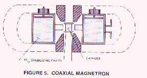 The theory of operation presented for a conventional magnetron applies equally to the anode-cathode region of the coaxial structure. However, the coaxial stabilizing cavity affords very significant improvements in overall magnetron performance.
SUPERIOR MODE CONTROL: Operating the cavity in the TE011 mode, and slot coupling alternate anode resonators to the cavity, produces anode control of such intensity as to permit the construction of coaxial magnetrons with many times the number of resonators that can be employed in a conventional type magnetron. This means lower cathode emission density, lower life and higher reliability.
REDUCED R.F. FIELDS IN THE ANODE: Whereas all stored energy in a conventional is confined to the vane resonators, in a coaxial magnetron approximately 85% of the total stored energy is contained in the stabilizing cavity. This means reduced r.f. field intensity at the vane tips, and less tendency to arcing.
IMPROVED FREQUENCY STABILITY: The redistribution of stored energy in the coaxial magnetron makes the high Q stabilizing cavity the prime determiner of magnetron output frequency. This means a lower pushing figure, a lower pulling figure, improved spectrum and reduced spurious emissions.
IMPROVED TUNING: In the conventional magnetron, tuning is accomplished by inserting inductive pins in the rear portion of each resonator, or by capacitive loading in the vane tip region.
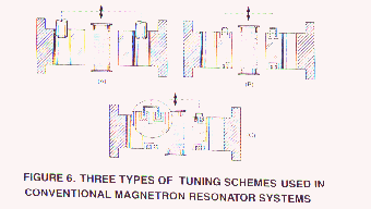 Both techniques represent an adverse perturbation to the natural geometry of the resonators which often results in power output variation with tuning, starting instabilities, increased susceptibility to arcing and a generally reduced operating lifetime for the magnetron. In contrast the coaxial magnetron is tuned by moving a noncontacting plunger in the stabilizing cavity (see Figure 5). The result is a tuning characteristic with no discontinuities, broad tunable bandwidth, and none of the disadvantages resulting from perturbations in the anode-cathode region.