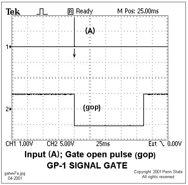
 Monophasic (Rtrn) input signal from
the Simulator at point (A) on the Signal
Gate circuit diagram and the gate opening pulse, (gop), that
opens the analog switch, U3, and causes the peak signal voltage to remain
on the 0.001 mF capacitor at pin #3 of follower, U4. This (gop)
pulse will serve a similar function for magnetic- and voltage-field signals
processed by the Track/Hold circuit
board.
Monophasic (Rtrn) input signal from
the Simulator at point (A) on the Signal
Gate circuit diagram and the gate opening pulse, (gop), that
opens the analog switch, U3, and causes the peak signal voltage to remain
on the 0.001 mF capacitor at pin #3 of follower, U4. This (gop)
pulse will serve a similar function for magnetic- and voltage-field signals
processed by the Track/Hold circuit
board.