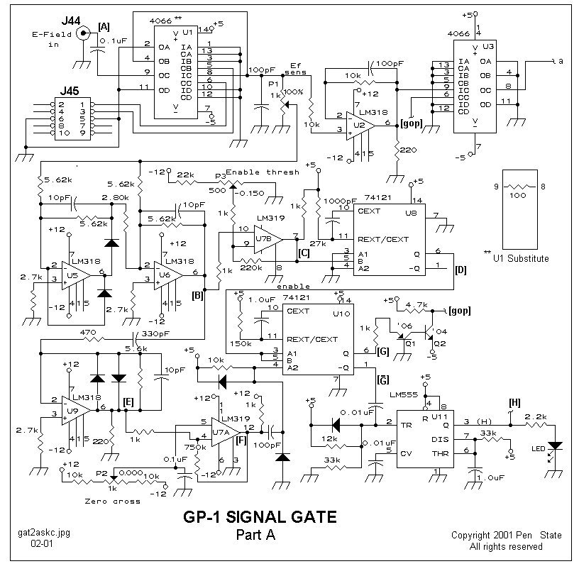
 Signal Gate circuit diagram,
Part A and Part B. Resistors shown with three significant figures are 1%,
1/4-watt carbon film. The remaining resistors are 5%, 1/4-watt carbon.
All capacitors in pF units are either ceramic COG types or dipped silver
mica. Polarized capacitors are 50 V tantalum. Rail 0.1uF bypass capacitors
are ceramic Z5U; the remaining capacitors are 50 V film. Trimming pots,
P1 through P5 are 6-mm cermet. Voltage levels shown at each trim pot are
approximate initial settings prior to final adjustment; see text. Parenthesis-enclosed
bold letters ((A), (B), etc) designate points where waveforms
may be found when the Signal Gate is driven by the Simulator.
The U1 Substitute, a 100-ohm resistor mounted on a 14-pin DIP header plug,
replaces U1, a 4066, when the Noise Gate is not used. Note (Spring 2001): U1 substitute resistor connection corrected to between pins 9 and 8. Also, power supply voltage to U11 is +5 volts.
Signal Gate circuit diagram,
Part A and Part B. Resistors shown with three significant figures are 1%,
1/4-watt carbon film. The remaining resistors are 5%, 1/4-watt carbon.
All capacitors in pF units are either ceramic COG types or dipped silver
mica. Polarized capacitors are 50 V tantalum. Rail 0.1uF bypass capacitors
are ceramic Z5U; the remaining capacitors are 50 V film. Trimming pots,
P1 through P5 are 6-mm cermet. Voltage levels shown at each trim pot are
approximate initial settings prior to final adjustment; see text. Parenthesis-enclosed
bold letters ((A), (B), etc) designate points where waveforms
may be found when the Signal Gate is driven by the Simulator.
The U1 Substitute, a 100-ohm resistor mounted on a 14-pin DIP header plug,
replaces U1, a 4066, when the Noise Gate is not used. Note (Spring 2001): U1 substitute resistor connection corrected to between pins 9 and 8. Also, power supply voltage to U11 is +5 volts.