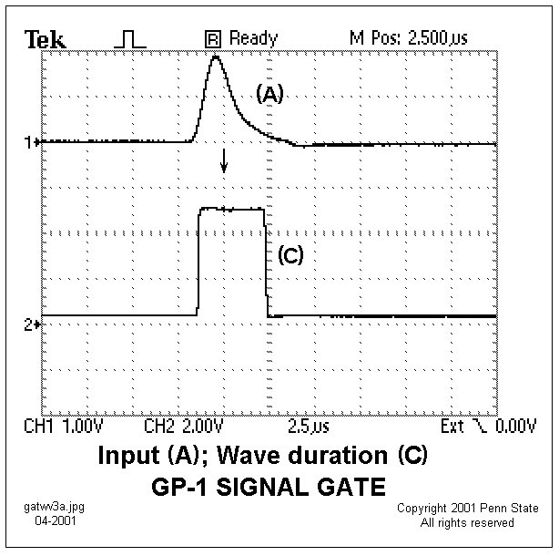
 Monophasic input signal from
the Simulator seen at point (A) on the Signal
Gate circuit diagram and output of Schmitt trigger, U7b, seen at (C).
The leading edge of (C) marks the foot of the input wave that exceeds
the threshold set by P3. This leading edge triggers the following enable
pulse generator, U8.
Monophasic input signal from
the Simulator seen at point (A) on the Signal
Gate circuit diagram and output of Schmitt trigger, U7b, seen at (C).
The leading edge of (C) marks the foot of the input wave that exceeds
the threshold set by P3. This leading edge triggers the following enable
pulse generator, U8.