When delivered, the laser diode is wrapped in aluminium foil. Do not unwrap the diode before reading the following instructions.
Have at hand a 100 mm length of fine copper wire, such as a single strand removed from a length of hook-up wire.
If you do not have a conductive wrist strap and cable designed for use when handling CMOS devices, devise an equivalent using a length of hookup wire. Connect the end of the wire to a reliable ground such as a cold water tap.
Hold the still wrapped body of the laser diode in one hand. Remove the aluminium foil from the laser diode leads using the other hand. Spread the laser diode leads slightly so they diverge. Wind the length of fine copper wire around and around all three leads, so they are shorted together.
This shorting wire must be left in place until the laser diode has been soldered into the otherwise completed PCB.
The laser diode must be glued into the housing to provide adequate heat transfer and cooling for the diode. If it is not glued in, or run without the housing then its life will be dramatically reduced.
Check that the laser diode fits neatly into the laser diode housing assembly. If necessary, scrape out the housing a little using a Stanley knife until the laser diode seats squarely and without forcing.
Mix a small amount of two-part epoxy adhesive (eg. 5 minute Araldite). Spread a thin film of this onto the outer edge of the flange of the laser diode. Fit the laser diode into the housing assembly, ensuring it seats correctly.
Leave the laser diode and housing assembly aside.
Solder all the components except PD1 and the laser diode to the board in accordance with the printed overlay. "LINK" on the PCB overlay marks a wire link. Use the IC sockets provided. Ensure all components are orientated correctly.
Solder three offcuts from resistor leads into the three holes marked LDK, PDA and PDK/LDA. Trim these to leave about 5 mm protruding from the top surface of the PCB. These will later be soldered to the laser diode leads as described in "Fitting the Laser Diode"
Bend the leads of PD1 (which is in a clear 5mm LED package) about 3 mm from the package and solder it into position so that its axis is 5 mm above the surface of the PCB. The flat on the diode flange marks the cathode.

Solder four offcuts from resistor leads into the four unmarked holes in the area bounded by PD1, R4 and Q1. Trim these to leave about 8 mm protruding from the top surface of the PCB. These will be soldered later to the shield which is fitted over PD1.
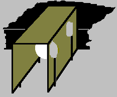
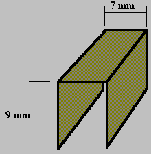
Bend the square of brass sheet into a square-cornered "U" shape with the dimensions shown in the sketch. This is the shield for PD1.
Fit the shield over PD1, inside the resistor lead offcuts and with one end of the shield hard up against the socket of U3. Solder the leads to the shield.