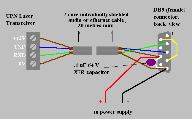
Signal conductors (TXD and RXD) between the computer serial port connector and the UPNLT should be shielded.
The power supply to the UPNLT (or a switch controlling the power supply) should be near the computer, as the UPNLT initialising string must be sent by the computer within a few seconds of powering up the UPNLT.
Dual independently-shielded audio or ethernet cable may be used to provide both signal and power connections as shown in the following circuit and diagram. The shield for the TXD conductor is used for the +12V supply. This arrangement minimises the wiring, but requires a capacitor inside the DB9 connector.
The arrangement shown raises CTS when the UPNLT is powered up. This can be sensed by the initialisation software, so it can determine the appropriate time to send the initialisation string.
DSR and DTR should be interconnected in the DB9 connector to provide the DSR signal for software which requires this.
All exposed shielding braid must be sleeved with shrinksleeve or similar to avoid short circuiting the power supply.
If the power supply is not short-circuit protected then a fuse must be included in the power supply positive lead. This fuse should be rated at 100 mA.

