
TDR Tutorial and Riser Bond TDR Product Review
Waveform Analysis
A great variety of waveforms may be encountered. This is due to the various applications, and electrical and environmental characteristic differences found in the wide variety of cables that exist today. Following are examples of some waveforms which may be encountered when viewing a traditional waveform TDR.

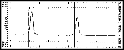
A reflection with the same polarity indicates a fault with OPEN (high impedance) tendencies. The reflection shown at the second cursor is a COMPLETE OPEN.
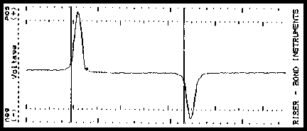
A reflection with the opposite polarity indicates a fault with short (low impedance) tendencies. The reflection shown at the second cursor is a DEAD SHORT.
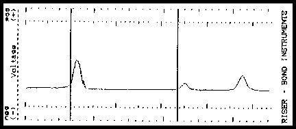
The middle reflection at the second cursor is a PARTIAL OPEN followed by a COMPLETE OPEN (end of the cable). The more severe the fault, the larger the reflection will be.
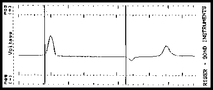
The middle reflection at the second cursor is a PARTIAL SHORT followed by a COMPLETE OPEN (end of the cable). The more severe the fault, the larger the reflection will be.
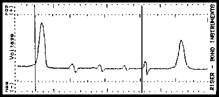
Due to attenuation (cable loss), the reflections caused by each of these equally spaced yet identical taps are progressively smaller. A larger reflection (second cursor) beyond a smaller reflection may indicate an undetermined or faulty tap.
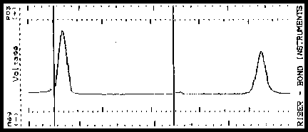
Two sections of coaxial cable with a barrel connector shown at the second cursor. The amount of reflection caused by the connector is directly proportional to the quality of the connector and connection.
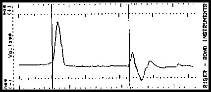
An unpowered line extender amplifier will cause a major reflection a the amplifier. The TDR signal will stop at the amplifier, but other reflections (ghost images) may appear beyond the amplifier.
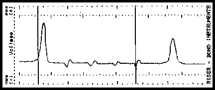
Coaxial taps (both indoor and outdoor) will cause reflections along the waveform. The quality and value of each tap determines the amount of reflection.
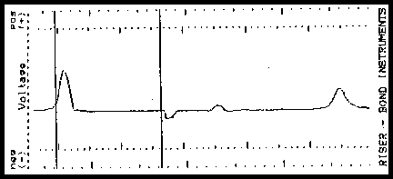
A splitter or directional coupler can be identified although accurate measurements are difficult due to multiple reflections. The second cursor identifies the splitter. The two reflections following are the ends of each of the two segments.
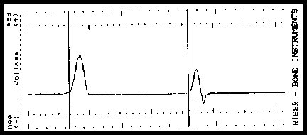
A high resistance joint or splice will produce an "S" shaped reflection. A high impedance upward reflection will be followed by a lower impedance downward reflection.
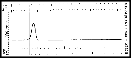
A properly terminated cable will absorb the TDR signal resulting in no reflection. Faults prior to the termination may show up as reflections along the waveform. If a terminator causes a reflection, the termination may be bad.
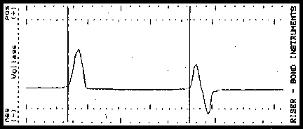
Testing through to an antenna usually results in an "S" shaped reflection, although reflections can vary greatly depending on the antenna.
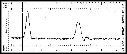
Testing tower cables with antennas can be challenging due to energy induction from high RF areas shown on this waveform. Stepping through various noise filter settings will result in a "cleaner" waveform.
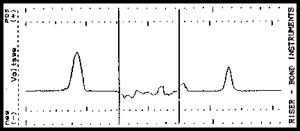
A water soaked cable will display a waveform with a downward slope indicating the beginning of the water and an upward rise at the end of the water . Generally, the area in between the two reflections will appear "noisy".
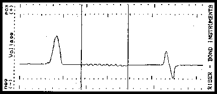
A wet section of cable is clearly seen on this waveform.
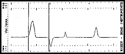
A bridge tap will appear as a negative or downward reflection followed by a positive reflection (caused by the end of the tap). Due to the multiple reflections, it is difficult to analyze results when testing through multiple taps.
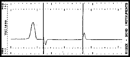
Crossed or split pairs: On twisted pair cable, a split may appear as an upward or downward reflection. The resplit will appear as a reflection of the opposite polarity.
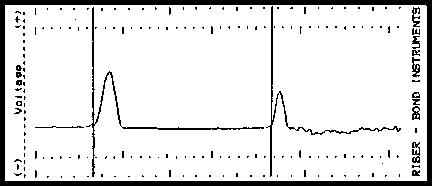
A telephone load coil will cause a high impedance upward reflection (similar to a complete open). A TDR signal generally will not test past a load coil.
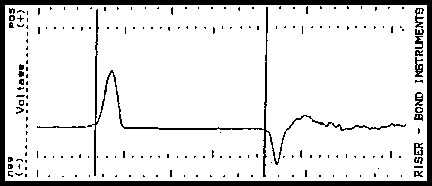
A telephone build out capacitor causes a low impedance downward reflection (similar to a short) followed by a smaller positive reflection.
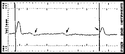
Mechanical inner-connectors (known as bullets) connecting sections of broadcast transmission lines sometimes burn open causing power outages. These bullets as well as other transmission line faults can be detected by a TDR.
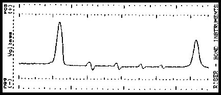
All types of twisted pair and coaxial LAN systems can be tested with a TDR. It is best to test for discontinuities in the cable if there is no traffic or power present. This waveform shows a section of unpowered cable with four transceivers installed.
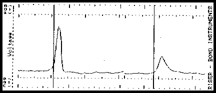
Pulse waveforms 1, 2, and 3 illustrate how only one setting can change the way a waveform appears. All three waveforms are of the same cable. Only the pulse width setting of the instrument has been changed.
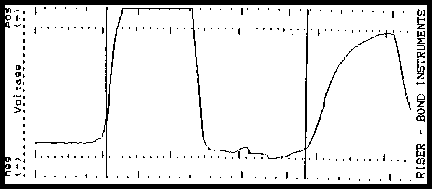
The width of the output pulse is also referred to as the blind spot or dead zone. It is more difficult to "see" a fault when it is contained within the blind spot.
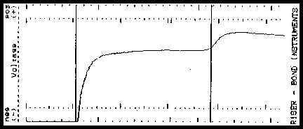
The larger the pulse width, the longer the blind spot. Note how the output pulse, and thus the blind spot, is progressively larger in samples 1, 2, and 3.
Any comments or questions regarding this specific page?
Please feel free to sign our Guest Book
![]()
|
To be contacted for a confidential consultation please E-mail: jmatk@tscm.com
or send a letter via US Mail to:
or call:
URL: http://www.tscm.com/ |