INTRODUCTION
This section describes an electronic compass option that can be added to the serial RS232 interface, or operated as a separate, autonomous compass in some other application, not related to the Doppler. When employed with the Doppler, it provides a means to automatically update the vehicle heading, ( without operator intervention ) resulting in a fully - stabilized azimuth display. At this time, the compass described here has been assembled and tested ( successfully ) on the bench, and a very brief field test was performed successfully in August 2000.
A more extensive field test was later performed with the Palm PDA display, ( and the "mini-antenna" ) and demonstrated clearly the virtues I expected of it... "hands off" updates of vehicle headings, which allowed the "vector summing" routines of the display software to operate at best efficiency. ( explained below )

The primary virtue of a compass - stabilized display lies in the fact that relieves the operator of a very burdensome “chore”... In order for the display software to “accumulate” DF bearings from a signal, and “pump up” the resulting display vector, the bearings from that signal must remain steady / constant. ( within the window set by SECTOR ) This is a problem, because the DF ( by its nature ) generates only RELATIVE bearings, so any change of vehicle heading will cause the ( reported ) DF signal bearing to change by an equal amount, in the opposite direction.
Operation without a compass is possible, by using the left / right ARROW keys on the numeric keypad, ( to enter changes of vehicle direction ) but this “chore” can consume a large portion of the operator’s time and attention... it requires that the DF operator exhibit faithful, vigilant attention to the vehicle heading, always watching for changes of vehicle direction.
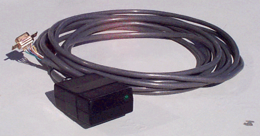
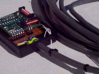
The compass sensor described here must be housed in a separate enclosure, and connected to the RS232 board by means of a 7 - conductor ( + shield ) cable. It is preferable to mount the compass sensor in ( or near ) the center of the vehicle roof, so that the surrounding ( magnetic ) mass is approximately equal in all directions. If it is mounted on the antenna ground plane, keep it away from magnetic screws, ( or other magnetic hardware ) used in the construction of the DF antenna.
The compass employs an OEM electronic compass “module”, manufactured by Precision Navigation, of Santa Rosa California, and available from Jameco Electronics, for US$ 50. The module is a model “Vector 2X” and you can click [HERE] to see the basic specs for it, at the company website.

A detailed data sheet is also available, ( in .pdf "Adobe Acrobat" format, 310 KB ) if you click [HERE]
The company website ( main page ) is : [www.precisionnavigation.com/index.html]
The Vector 2X can be operated in a vareity of different configurations, depending on the needs of the end-user. In this particular application, the module is configured to operate in the “low precision” mode, with BCD output, and “polled” operation, as well as “slaved” data clocking, and compass orientation “right side up”. The output message consists of 16 bits, ( 6 are not used ) generated in serial form, with 5 volt CMOS levels. A “high precision” mode can be achieved with the addition of a single wire “strap” at the compass, but this option has not ( yet ) been investigated by me... it will cut the update rate ( from the compass ) in half, ( not really a problem ) and probably requires the creation of a compass “correction table”, to be truly useful.
GENERAL PROFILE
To employ the compass data, ( and operate the compass ) the PIC code for the RS232 interface must be enhanced with the addition of several new routines, and changes to a few of the original routines. Similarly, the IBM PC display software must be enhanced with the addition of several routines to recover the ( new) compass data from the RS232 link, and employ it. New versions of the PIC source and object code are ( therefore ) provided in this section of the website, as well as a new version of the IBM PC display software.
Regarding hardware changes, the compass employs several ( previously unused ) pins on the PIC RS232 chip.... At this time, no changes in the PCB artwork for the RS232 board ( to accomodate the new wires ) have been performed, and ( frankly ) none are anticipated... there isn’t much room left for any new wire pads, and NONE for the PCB tracks required to feed them...
There is also no PCB artwork for the compass itself... there wouldn't be much on it, anyway... just the footprint of the Vector 2X module, and some wire pads... use some perforated breadboard material, (0.1 x 0.1 inch grid ) and "hand wire" it... it might be wise to provide IC socket pins for the module, in case it ever fails.