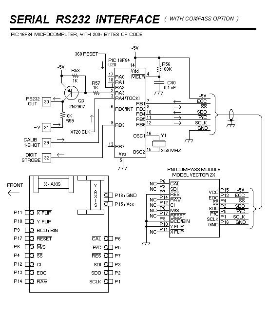
This section describes the compass circuit, and provides a schematic for connecting the compass to the PIC chip :

The cable must have at least 7 conductors, ( plus a shield ) but more wires are probably wise... there are a few features on the compass that are not implemented in this design, and extra wires would make future implementation much easier... one would probably be a RESET signal, in case the compass computer “hangs up” for any reason. Another is the use of the CAL input for the compass. ( this feature is described in the compass spec sheet, but not mentioned anywhere else on this website... take a look at it ) Obviously, disconnect plugs would be a good idea, both at the compass and at the DF unit...
Some care must be paid to the compass housing and installation.... be careful about your choice of hardware... use non-magnetic hardware, such as brass or stainless screws, everywhere within 6 inches of the compass, minimum. Check the connector as well, including the pins... use a “pigtail” if any part of the connector is magnetic.
The compass can probably be mounted inside the vehicle, but you won’t get any sympathy from me if the resulting errors are horrible... Go ahead... mount that sucker directly above that big, juicy SPEAKER MAGNET in the center of your dashboard... Why does the heading “bounce around” when I turn on the windshield wipers ? Rear window de-fogger ? Hey... not a problem ! Use a mag-mount on the roof... SURE !