THE CIRCUIT
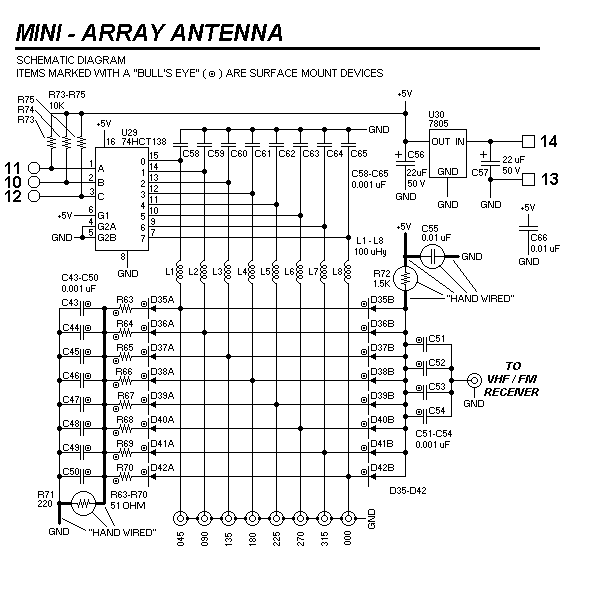
Here is the schematic diagram of the mini - antenna array. The PIN diodes
are SMT devices with two diodes ( series connected ) per device. Aside from
the addition of 50 ohm SMT load resistors for each antenna, the schematic
is almost identical to that of the original antenna board, although ( obviously )
several component values and part numbers have changed.

CIRCUIT DETAILS
Some of the circuits must be "hand wired" for reason previously explained. In
the schematic shown above, these circuits are identified with BOLD wires and
CIRCLED components. Surface mount devices are indicated with a "bull's eye" symbol.
[HOME PAGE]
[NEXT PAGE]

