Greetings
conducted by: Richard L. Measures, AG6K - telephone, [805] 386-3734 (voice). To penetrate the telemarketer filter, ring twice, hang up, press "Redial". If I am home, I will answer. . If not, please leave your telephone # and I will return the call.
6455 La Cumbre Road, Somis, CA, 93066 / E-mail:
2@mail.vcnet.com
last revised 7 July, 2002.
What's new and semi-new?:
High Potential
Tester (a.k.a. 'high-pot.')
Circuit Improvements
and Maintenance Procedures for the TS-830S
Circuit
Improvements for the TS-430S
Circuit Improvements
for the TS-440S
Circuit
Improvements for the TL-922
[condensed version]
QSK for the TL-922
and SB-220 With Circuit Improvements for the TL-922
Fyler, G. W. ''Parasites in Transmitters'', Institute of Radio Engineers journal. Sept. 1935. Conclusions.
Original Manuscripts, updated where appropriate
"Improved Anode Parasitic suppression for Modern Amplifier Tubes", {October 1988 QST,}
"Adding 160 Meters to HF Amplifiers" {1/89 QST}
"A Balanced Balanced Antenna Tuner" {2/90 QST}
"Circuit Improvements for the Heath SB-220 Amplifier" (updated manuscript for Nov.-Dec., 1990 QST article).
"The Nearly Perfect Amplifier" (1/94 QST)
Dovetron's 10m mod for the TL-922, page 1, and page 2.
What follows is the updated
manuscript I wrote under contract for the amplifier chapter (13) of
the 1995 ARRL Handbook
If you find a glitch in Amplifiers, a fuzzy explanation, a technical error, or a typo, please let me know. If you think I left something important out, please say so.
The title 'Amplifiers' is somewhat
misleading. Only linear amplifiers are discussed in detail. If you
are interested in building a Class B or Class C amplifier,
'Amplifiers' is not going to be of much help.
Low VHF-Q parasitic suppressor retrofit-kits for most types of amplifiers -- both mfg. and home-brew. Price List--Information Sheet
High-speed switching parts-kit for retrofitting an existing non-QSK amplifier. p/n 47 (See January, 1994 QST , "The Nearly Perfect Amplifier", page 33---or see Figure 7 - 7B above) The kit includes the Matsushita 1mS RF reed-relay (RY2), the NEC optoisolator (Q2), the 6A transistor (Q1), two (1 plus a spare) 1500w 51v transient voltage suppressors (D1), needed resistors/capacitors and a 300v 0.5a NPN switch transistor for controlling the amplifier with a radio that supplies +LV on TX to key the amplifier. Untested, used, Jennings RJ-1A RF output vacuum-relays (RY1) are available from Fair Radio Sales 419-227-6573. The price is approximately $35 for a used RJ-1A. . // The price of the parts kit is $21 plus $1 for shipping to US addresses .// . I recommend testing the RJ-1A before use. A relay with a good vacuum will withstand at least 3500v across the open contacts -- with under 2 micro amperes of leakage. Note: A bad vacuum in RY1 can destroy RY2.. High Speed Relay Mounting Instructions.
High-reliability, high-stability MOF
resistors for electrolytic filter capacitor equalizer R service.
Matsushita, 100k-ohm, 3w, 500V max.
matched within 0.05%, part number 86, $0.48 each.
We no longer sell telephone RFI
filters. However, you can buy the parts for them from Mouser
Electronics [1-800-346-6873]. The part number for the 470 micro-Henry
inductor is 43LS474. The current price for 100 is $29. 100 inductors
will build 50 single-section filters or 25 double-section filters.
The value of the [1000pF to 3000pF] capacitors is extremely
non-critical. The capacitors have little effect on the suppression
ability of the filters--except perhaps on 10m. Put one inductor in
series with each side of the telephone line. The filter should be
close to the telephone. If the interference persists after one filter
is installed, try a double-section filter. Phone filter
Diagram.......phone filter
Instructions.
We no longer sell HV bypass caps because our cap supplier stopped carrying them.
League Fatigue
- The Background Story behind the following story-
On page 24 in the February, 1996 issue of QST, Editor Mark Wilson, AA2Z, writes:
"The rebuttal that Rich provided was, in our
view, repetitious of his articles that were previously published in
QST. Readers who are interested in knowing more about his design
philosophy have a wealth of material in print with which to
work."
Maybe the Rebuttal is
repetitious of the QST articles, or perhaps not. I thought that the
people who read QST might like to have the opportunity to decide this
matter for themselves. After all, Mark Wilson works for them. It's
probably a good idea for an employer to check up occasionally on
employees.
Mark Wilson said, "We should have sent 'The
Nearly Perfect Amplifier' for technical review and dealt with any
questions about its accuracy prior to publication, ...." Apparently,
Mark expects people to believe that QST does not perform an adequate
technical review of articles with its own technical review group.
Unsliced bologna. No article gets accepted without the approval of
QST's technical review group. Mark seems to have forgotten that "The
Nearly Perfect Amplifier" did receive a final technical review just
before it went to the printer. The final reviewer was QST's present
Editor, Mark Wilson.
Mark Wilson suggests that there were some technical errors in the
article -- but he doesn't mention a specific error to support his
allegation. So far, I have become aware of one technical error in the
article. Eimac recommends a Q of 5, Not a Q of 2, for the tuned input
of a G-G amplifier. The person who found the error was the author of
the article. If you find another technical error in the article,
please telephone me, collect if you like, or E-mail me.
I apologize for the length of the Rebuttal. It is longer than I would
have liked. However, the Rebuttal is designed to address each point
of contention in the September. 1994 QST [pages 71-74] critique.
There was much material to cover. The critique by the six
"contributors"/critics (Fred Telewski, WA7TZY; Tom Rauch,W8JI; Reid
Brandon,W6MTF; Bill Clemow, KE7CX; John Fakan, KB8MU; and Steven
Katz, WB2WIK) amounted to 5500 words -- an all-time record for
QST.
A letter from
Eimac® (text) is mentioned in
the Rebuttal. Letter from
Eimac® (photocopy)
link to
'The Somis Library' (not related to amateur radio)
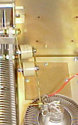
photos of Plywood Box; Top, Front , Chassis , Power Supply