Buy and download my eBook: The
PID Control Algorithm:
How It Works and How To Tune It. 58pp
MS Word 97 or .pdf file
only $9.50.
Get more details, buy, and download
| ControlSim The PID controller and process simulator based on MS Excel spread sheets. $45.00 | Click here to get more details, buy, and download |
Buy and download my eBook: The
PID Control Algorithm: |
Get more details, buy, and download |
Chapter 3
The PID algorithm
Action
PROCESS ACTION
Defines the relationship between changes in the valve and changes in the measurement.
DIRECT Increase in valve position causes an increase in the measurement.
REVERSE Increase in valve position causes a decrease in the measurement.
CONTROLLER ACTION
Defines the relationship between changes in the measured variable and changes in the controller output.
DIRECT Increase in measured variable causes an increase in the output.
REVERSE Increase in measured variable causes a decrease in the output.
The controller action must be the opposite of the process action.
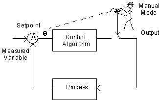
Auto/Manual
Manual Mode:
The operator adjust the output to operate the plant.
During startup, this mode is normally used.
Automatic Mode:
The control algorithm manipulates the output to hold the process measurements at their setpoints.
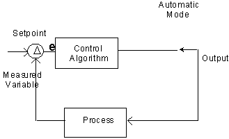
This should be the most common mode for normal operation.
Key concepts
The PID control algorithm does not "know" the correct output to bring the process to the setpoint.
• It merely continues to move the output in the direction which should move the process toward the setpoint.
• The algorithm must have feedback (process measurement) to perform.
The PID algorithm must be "tuned" for the particular process loop. Without such tuning, it will not be able to function.
• To be able to tune a PID loop, each of the terms of the PID equation must be understood.
• The tuning is based on the dynamics of the process response.
The PID Control Algorithm
The PID control algorithm comprises three elements:
Proportional - also known as Gain
Integral - also known as Automatic Reset or simply Reset
Derivative - also known as Rate or Pre-Act (TM of Taylor Instrument Co.)
The algorithm is normally available in several combinations of these elements:
Proportional only
Proportional and Integral (most common)
Proportional, Integral, and Derivative
Proportional and Derivative
We will examine each of the three elements below:
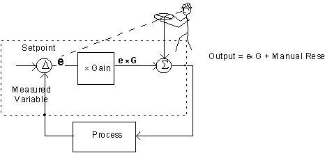
Proportional
E = Measurement - Setpoint (direct action)
E = Setpoint - Measurement (reverse action)
Output = E * G + k
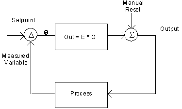
The output is equal to the error times the gain plus the manual reset.
If the manual reset stays constant, there is a fixed relationship between the setpoint, the measurement, and the output.
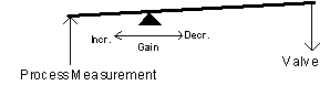
Proportional—units
The proportional or gain term may be calibrated in two ways:
Gain and Proportional Band
Gain = Output/Input
Increasing the gain will cause the output to move more.
Proportional band is the % change in the input which would result in a 100% change in the output.
Proportional Band = 100/Gain
We will use gain in this document.
Proportional—Output vs. Measurement
 (Reverse acting)
Proportional only control produces an offset. Only the adjustment of the manual reset removes the offset.
Proportional—Offset
Offset can be reduced by increasing gain.
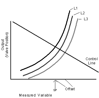
Proportional control with low gain
Proportional control with higher gain
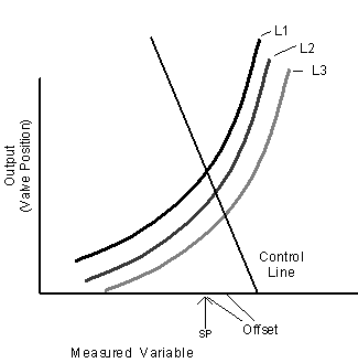
Proportional—Reducing offset with manual reset
Offset can be eliminated by changing manual reset.

Proportional control different manual reset
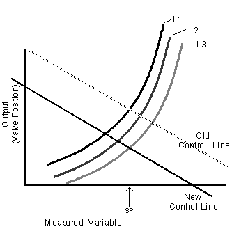
Adding automatic reset
With proportional only control, the operator "resets" the controller (to remove offset) by adjusting the manual reset:
This manual reset may be replaced by automatic reset which continues to move the output whenever there is any error:
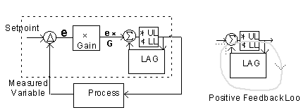
This is called "Reset" or Integral Action.
Note the use of the positive feedback loop to perform integration.
Reset or integral mode
Reset Contribution:
Out = g
X Kr X integral of error where g is gain, Kr is the reset setting in repeats per minute.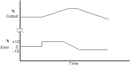
Units used to set integral or reset
Assume a controller with proportional and integral only.
Calculation of repeat time: (gain and reset terms used in controller)
With the error set to zero (measurement input = setpoint), make a change in the input and note the immediate change in output. The output will continue to change (it is integrating the error). Note the time it takes the output to, due to the integral action, repeat the initial change made by the gain action.
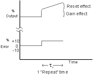
Some control vendors measure reset by repeat time in minutes. This is the time it takes the reset (or integral) element to repeat the action of the proportional element.
Others measure reset by "repeats per minute".
• Repeats per minute is the inverse of minutes of repeat
This document will use repeats per minute.
Derivative
First used as a part of a temperature transmitter ("Speed-Act™" - Taylor Instrument Companies) to overcome lag in transmitter measurement.
Also known as Pre-Act and Rate.
Derivative Contribution:
Out = g
x Kd x de/dt where g is gain, Kd is the derivative setting in minutes.
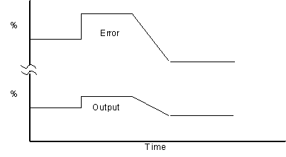
Response of controller with proportional and derivative:
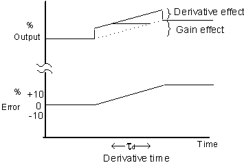
The amount of time that the derivative action advances the output is known as the "derivative time" measured in minutes.
All major vendors measure derivative (Derivative, Rate) the same.
Complete PID response
Non-Interactive (text book) form:
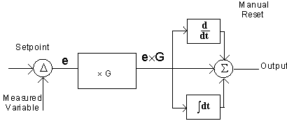
Out = G
(e + R+ D )Where
G = Gain
R = Reset (repeats per minute)
D = Derivative (minutes)
Note: See Interactive vs. Noninteractive (below)
back to index go to chapter 2: the control loopgo to chapter 4: more about the PID algorithm
| Buy and download my 21 page e-book on the PID algorithm. MS Word 97 format only $5.00 |
 |
| Buy and download my 25 page e-book on the PID Tuning. MS Word 97 format only $6.00 |
|