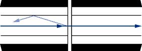
Return reflections occur at a change in the index of refraction.
Air gaps between mated fibers can be a major source of reflections.
Title: Introduction to Fiber Optic Networking - Contents
Author: AMP, Inc.
Company: AMP, Inc.
Alignment: The Key to Low Loss
Interconnection is a critical part of a fiber optic link. The job of a connector or splice is to provide low-loss coupling of light through a juncture. Low loss is the result of precise alignment of the two fibers being joined. Any misalignment of the two fiber cores increases the loss.
Losses stem from three sources:
2. Tolerances in the fiber. The fiber should have a perfectly round core centered exactly within a perfectly round cladding. As these depart from perfection, loss is increased.
3. Different fiber types. Loss is increased if the receiving fiber has a smaller core or NA. In most premises cabling applications, the same type of fiber is used throughout the installation, so these losses are not a concern.
Insertion loss has been decreasing steadily over the years. In the early days of fiber optics, a loss of 1.5 dB was considered a reasonable target. Over the years, the average insertion loss was lowered to 1 dB and then 0.6 dB. Now it is around 0.3 dB.
As the insertion loss problem was solved, attention turned to ease of use, lower costs, and standardization. A number of connectors have evolved over the years.
PC: Polishing Correctness
Singlemode connectors present an additional consideration: return reflections. When two fibers are separated by an air gap, optical energy will be reflected back toward the source. These reflections - termed Fresnel reflection - occur at both the glass/air interface as the light leaves the first fiber and the air/glass interface as light enters the second fiber. A flat ferrule end surface can allow an air gap. The light reflects directly back into the fiber core, where it can propagate back to the light source.

This reflected energy is described by the term return loss. The lower the reflected power, the higher the return loss. In a singlemode interconnection with flat end finish, this loss may amount to -11 dB - that is, the reflected energy is about 11 dB below the incident energy. If 500 microWatt of energy reaches the fiber end, about 40 microWatt will reflect back toward the source. This level of energy is sufficient to interfere with operation of a laser diode and cause errors.
By rounding the end finish during polishing, return loss can be lowered to over -30 dB - the 500 microWatt now reflects only 0.5 microWatt toward the source.
Two factors contribute to this dramatic reduction:
Second, the rounded end means that light no longer reflects directly back toward the source (the angle of reflection is equal to the angle of the incident light). It reflects back at an angle and is usually lost from the fiber. The rounded finish first cuts the amount of light reflected and then redirects what is reflected so that it does not reach the laser diode. This approach is called a physical contact or PC-end finish.
Return reflection can be lowered even further with the angled PC (APC). This angle reflects the light into the cladding rather than back down the core.
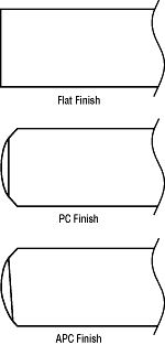
The variations in PC finishes provide different levels of return loss, typically defined as:
An accepted part of fiber optics, cleanliness is especially important with PC connectors. A speck of dirt on the high side of the curve can prevent the fibers from touching or create a scratch. You have an index of refraction mismatch and higher return loss: -11 to -16 dB instead of -30 to -40 dB.
Types of Connectors
For a premises cabling application, four connectors are of interest: ST-style, SC, FDDI, and ESCON connectors. Most connectors are based on a 2.5-mm-diameter ferrule, which secures and aligns the fiber. Ferrules are typically made of ceramic, polymer, or stainless steel.
Ferrule material is less a consideration in most applications. Gone are the days when ceramic ferrules were decidedly superior in optical performance to polymer and stainless-steel ferrules. The polymer ferrule was once considered the low-cost and lower-performing sibling of the "high-performance" ceramic ferrule. With improvements in polymer materials and better process controls, some of today's polymer-based connectors feature performance indistinguishable from many ceramic-based connectors. Equally important, today there is less of a price difference between ceramic, polymer, and stainless-steel connectors.
The result: more choices with less distinction between them. Durability, however, remains one difference. Stainless steel offers the highest durability, because it is a very rugged material without the brittleness of ceramic. In contrast, polymer offers less durability - typically between 200 and 500 cycles, which is still a high cycle life by most people's definition.
ST-style Connectors
ST-style connectors use a quick release bayonet coupling, which requires only a quarter turn to engage or disengage. Built-in keying provides repeatable performance since the connector will always mate with a coupling bushing in the same way.
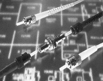
The ST-style connector was the predominant connector during the late 1980s and 90s, being the connector of choice for premises cabling, networking, test equipment, and many other applications. It is, however, being superseded by the SC connector in some standards.
SC Connector
Emerging as the general-purpose connector of choice for premises cabling and network applications, the SC connector uses a push-pull mechanism for mating. The basic SC connector consists of a plug assembly containing a ferrule. These plugs mate in a connector housing that aligns the ferrules. One advantage of the SC connector is that several plugs can be joined together to form a multiposition connector. This multifiber capability is especially handy for building duplex (two-position) connectors. One fiber can carry information in one direction, while the other fiber can carry information in the other direction. The connectors are keyed to prevent mismating.
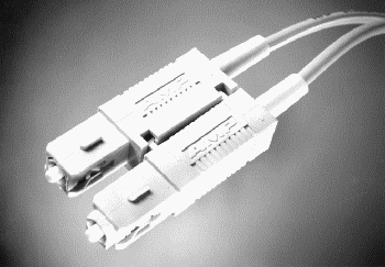
FDDI Connector
The FDDI connector is a two-channel device using two ferrules and a side-latch mechanism. A rigid shroud protects the ferrules from accidental damage, while a floating interface ensures consistent mating without stubbing. Different keying arrangements are provided to key the connector to different FDDI requirements. FDDI connectors are not restricted to FDDI applications.
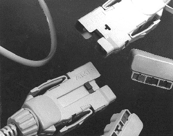
ESCON Connector
The ESCON connector, used in IBM's Enterprise System Controller, is similar to the FDDI connector, but features a retractable shroud.
Terminating the Fiber: To Epoxy or Not to Epoxy
If performance isn't the issue it once was, ease of use is.
Some connectors use epoxy. Their approach to termination is: prepare the fiber, apply epoxy, assemble the fiber in the connector, wait for the epoxy to cure, cleave the fiber protruding from the end of the ferrule, and polish the end finish.
Other connectors do not require epoxy. The epoxy step, in particular, is seen by many as a necessary evil. Not only do curing times slow productivity, but speeding the process means additional equipment like curing ovens to lug around. Fortunately, epoxyless connectors now offer reliable, fast terminations.
Epoxyless connectors have slashed application time from 10 or more minutes to less than 2. Epoxyless connectors are available in most flavors: for multimode and singlemode fibers; with ceramic, stainless-steel, or polymer ferrules; and with industry-standard ST-style and SC interfaces. Performance is equal to epoxy counterparts - and well within the bounds of application requirements.
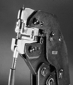
Installers like epoxyless connectors. Not only do all required tools - crimping tool, cleaving tool, and polishing plate - fit conveniently in a toolkit, there's no oven or ultraviolet curing device to carry around; mess and inconvenience are minimized. What's more, eliminating epoxy reduces the training required to terminate an optical fiber cable since the tools help ensure a proper termination. The absence of epoxy makes polishing faster and easier: epoxy is harder to remove than the small strand of glass that remains after cleaving.
By eliminating the mess of epoxy and simplifying termination procedures, epoxyless connectors make field installation easier and faster. In premises cabling and networking applications, epoxyless connectors make it easier for contractors to train installers, increase productivity significantly, and ease the migration from copper to fiber. They also eliminate epoxy fumes and spills on carpets.
The need for polishing is still with us: scribe-and-cleave methods alone have not yet proven effective.
Type   Coupling   Fibers    Style       Insertion Loss (dB)  Mating  Singlemode
                                       Multimode Singlemode  Cycles  Return Loss 					Multimode		Singlemode		(dB)
----  ---------  -------   ---------   ---------  --------   ------ -------
ST    Bayonet      1        Epoxyless       .4      .2        500     -
                            Ceramic         .3      .3       1000   < -40 dB
                            Polymer         .3       -        500     -
                            Stainless Steel .3       -        500     -
SC   Push/Pull 1-4, or more Epoxyless       .4      .2        500     -
                            Ceramic         .3      .3       1000   < -40 dB
FDDI  Latch       2         Ceramic         .5      .3        500   > -35 dB
                            Polymer         .3       -        500     -
ESCON Latch       2         Ceramic         .5       -        500     -
All connectors are epoxy crimp-style unless noted. Materials in "Style" column refer to ferrules.
Neatness Counts: Hardware Organizes Fiber
Any significant premises cabling installation runs the risk of chaos, with wiring closets becoming a rat's nest of tangled cables. Patch panels, enclosures, and distribution hardware bring order by providing a method of organizing fibers. One of the facts of life for premises cabling is moves, adds, and changes (MACs). People move around a company, companies expand (and contract), and groups come together and reform on a project-by-project basis. So the hardware should allow cables to be easily rearranged to reflect the latest organizational needs.
A wiring closet represents the organizational center of the premises cabling system. In the closet the patch panels and organizers are consolidated, along with network equipment such as hubs. All the building wiring runs into and out of the wiring closet, so it's here that neatness is most important.
Patch panels are rather straightforward. They simply are a panel that contains coupling adapters to allow cables to be plugged or unplugged. Most patch panels permit plugging on both sides to achieve maximum flexibility in arranging and rearranging the cables. Others provide cable management to keep the routing and placement of cable orderly.
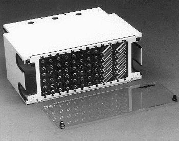
Distribution units and enclosures are similar to patch panels, except they provide additional space to organize fiber. Itss always a good idea to leave some extra fiber - this slack is then available if it becomes necessary to reterminate a connection. The distribution units provide an area to store the extra fiber in a large loop.
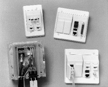
Beyond the wiring closet, wall and floor outlets provide the transition from the inner-wall cabling to the drop cables running to equipment. These serve the same purpose as the modular plug telephone outlet. One of the most popular variations is the AMP Communications Outlet, which uses modular inserts to accommodate coaxial, twisted pair, and fiber optic cabling. Interfaces are available in nearly every conceivable style to meet all needs.
