After building a few of the simple MK 484 receivers, and playing around with it a bit, I decided it still needed a bit more oomph in the station count ability. First I tried just adding a ground of some sort, and things picked up. Putting a balanced armature headphone in for the crystal earplug really helped too, but took it out of the kid radio class; parts prices started mounting. Feeding it with a signal inductively coupled from an antenna tuner worked nicely too, but there went the "no antenna" feature. Then I started looking at my collection of parts for kid projects that never got off the ground, and decided it might be neat to marry the MK 484 to the Audion type receiver. Both like a 1.5 volt power supply, and the audion circuit would give the signal a boost while accommodating a cheap set of dollar store walkman style phones. After a bit of fiddling around, this was the result:
Parts:
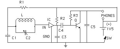
R1, R3 100 kohm
C1 0.01 uF (10 nF)
C3, C4, C5 0.1 uF
(100 nF)
R2 1000 ohm
Q 2n2222 (see audion
notes)
IC MK 484
C2 I used a 220 pF polyfilm
variable capacitor, but just make sure the value is compatible with the
inductor L.
L I used 90 turns of #32
enameled magnet wire close wound on a 5/16 inch x 1 3/4 inch ferrite core,
which gave me the 400 uH I needed to match C2.
Phones: all the notes
in the audion article apply.
Since R2 sets the proper voltage for AGC in the IC, it might pay to play around with this a little - don't go below about 500 ohms. With one of my sets, I found that it behaved nicely with the 1 k resistor and a battery salvaged from my son's Game Boy (1.3 V). With a new battery (had to sneak it past him), it developed oscillations in the upper half of the band, so I increased the value of R2 and it stopped. I finally put in a 2.2 kohm resistor, declared victory and quit. I guess if you want to do it right, you use a regulated power source, but that's where I draw the line. However, I might consider a value of 500 ohms for R2 and put a 0 to 2k pot in series with it to accommodate battery aging. Yeah that's even more parts, but sometimes ya' just gotta make one you can set on the table.
If your locals are too loud,
you have some options; a. detach the ground, b. turn the set
to point the antenna elsewhere
c. put a variable resistor
(pot) between the output of the IC and C4 - around 10k ought to do it
d. move
As with the basic 484 rig, this set lends itself well to pc or pseudo pc construction, using sticky copper tape or brass shim stock glued to a base for the soldering pads.
This set worked well for me picking up the locals and usual other daytime stations ordinarily heard on a superhet, and really brings the distant stations in at night. Its performance approaches that of a superhet, which, for a set with so few parts and ease of construction, such as no alignment or adjustments to make, it is a neat little radio. With a very high input impedance to the IC, it keeps the Q of the tank circuit high, and does not suffer as much from pulling and overload from strong locals as do many crystal sets and other simple tuned rf sets. I found that the so called ground connection can be a variety of connections, such as the screw on electrical switch plate covers, bare metal on lamps, the antenna for the cordless phone base station, and even a real ground.