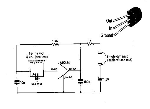
In 1970 Ferranti started the development of a single-chip AM tuner, and by 1973 it became widely available for use. The 414 is no longer in production, but a follow on IC, the MK484 recently became available, and incorporates essentially the same features. It is a 3 terminal device which packs ten transistors providing 3 stages of rf amplification with an input impedance of about 4 Megohms, and giving 72 dB of gain with about 30 millivolts of audio output (rms). Thanks to the editors of Practical Wireless a ham magazine in the UK, and Dr. Philip Miller Tate of Kingston University, who has probably built a dozen or so of these in one guise or another, and sent me one fully assembled, here is one adaptation of this versatile little chip which gives you a nice little portable radio which is stable and virtually idiot proof to build, needs only a 1.5 v battery, and requires a tiny thimble full of parts to give you near-superhet performance. Here is the schematic of the circuit that PW came up with:
The frequency range of the chip is about 200 kHz
to 3 MHz. The coil/capacitor selection for the tank circuit should
fall into this range. For small size and shirt pocket portability,
you can use a ferrite core coil as shown. I have tried it with a
variety of tank coils, and they all work fine. Notice there is no
antenna - don't need one. I have found that the set "likes" to have
a ground connection. You can improve reception somewhat with an external
antenna and ground, but do so lightly; I found that a small antenna coupling
coil connected to antenna and ground in the vicinity of the tank circuit,
loosely coupled, works nicely.
While the designers had in mind a pc board assembly,
I have found that "dead bug squashed flat" works well too; so did the PW
staff,
as you can see by the rendition on their Technical
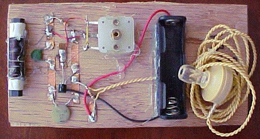
Features Page . Phil used a small masonite board and epoxied
brass strips on it to make his solder connections (see it at Xtal
Set Photos by Dr. Whiz). Mine was assembled on a 6 lug tie strip,
which was then screwed into a board.
Now for some notes and fashion tips on putting this
together and using it:
100 nF = 0.1 uF (that's a 104)
10 nF = 0.01 uF (103)
The dynamic earpiece mentioned can be one of the
balanced armature types found in sound powered headsets (and most telephone
earpieces - don't tell Ma Bell I told you). I used successfully magnetic
earphones; 2000 ohm phones, if used, can replace the 1 kohm resistor.
I also tried a 1 kohm dynamic earplug from Mouser, also replacing the 1
k resistor, and it worked, but it is not a very sensitive plug, and is
not recommended except "in town". I also used a high impedance crystal
earphone across the 1k resistor with good success - I think a 1.5 k resistor
worked a little better, however.
You can connect a small audio amp to this set, connecting
it across the 100 nF capacitor - the input capacitor to the amp should
be about 100 nF.
Did I mention that this chip incorporates automatic
gain control (AGC)? The resistance between the (+) side of the battery
and the junction of the 1 k and 100 k resistors determines this, and you
might want to play around with this a bit, depending on how you get the
audio out. If you feed an audio amp with the set, the 1k AGC resistor might
need to be adjusted, but don't go below about 500 ohms. The AGC and the
Q of the tank circuit pretty much determine the ability of this set to
perform as well as it does. Even with rather strong stations nearby,
you will be slowly tuning and hearing a strong station in the background,
all over the dial, so to speak (remember, this isn't a superhet), and then
a station will pop up clearly out of the background noise. You can
also null the strong locals a bit by turning the set so that its coil is
pointed in a quieter direction. This set might be neat to use with
a loop antenna for the coil.
You can get this set to oscillate (I did
it when playing around with the AGC), but you don't want it to. You
should separate the power and audio leads from the tuned circuit, and keep
your leads short (separated is perhaps more important than short - I used
long clip leads to connect different coil/cap combinations to the set).
Don't buy a new battery - this baby only draws a
half a milliamp when its cooking. With a spanking new alkaline battery,
the high gain front end is susceptible to oscillation, and a higher value
R1 might be needed.
Austin Hellier from down under posted this on Rap 'n Tap for those of you looking for some mods to this simple rig which he claims will improve its performance - takes only a couple of 1N914 diodes and a bit of wire to accomplish:
"Thought you might be interested in a couple
of mods for your MK484 receiver - these have proved very popular over here
in Australia - Dick Smith Electronics puts out their Funway 1 series, and
one of the projects is this kind of receiver, driven from a simple cell
made of zinc coated nails, copper strips and - good old Aussie beer...
Now to the mods - take two 1N914 diodes in
series from pin 1 to ground - this ensures no overvoltage to the chip -
then take a 1K5 resistor to the 1.5 volt battery. You can use a 6K8 resistor
instead, if you want to use a 9 volt battery.
Instead of using a single winding and parallel
polycap, I use an inductive coupling method. Five turns of telephone jumper
wire (brittle stuff, easy to work with though) and connect that between
the junction of the 100K/0.01u - the other end goes to pin 2. Both ends
of the main winding (50 turns around a 100 x 9mm rod in parallel with a
220pF cap)is then floating free from the rest of the circuit. This prevents
loading of the tuning circuit, prevents acoustic feedback, and the volume,
clarity and selectivity have to be heard to be believed - hope this helps
you and your students, club, friends etc."
I suspect that either of the two modifications will improve the set. However, the diode trick will cost you some battery life, and the inductive coupling does cut down on the sensitivity with the unadorned set.
You Elmers can go HERE for a layout and
construction instructions I use with my students.
Oh yeah, here is a picture of the "student model, without the battery
installed or the capacitor knob. The base shown is 3 x 6, but I use
3 x 5 with the students; this is the prototype. Assembly time with
prepared coil and capacitor was about 1.5 hours for very novice builders.
Suppliers of the MK 484:
Kanga
, a UK supplier will sell you the chip for a pound note plus S&H.
Dick Smith Electronics has it listed at $2.29 AUS; get ten, they're
cheap, and get your cub scout pack involved, or have a building contest
at your next ham club meeting.
Modules
& Hard-to-Get Items good price - buy a bunch
Ocean State Electronics
has a pricey ZN414 listed.
I am unaware of any US suppliers of the MK484.
If you run across any 414s, you can build the set
here, just remembering that the pinout for the 414 in the TO92 case is
reversed from the 484 above, center is still input. For the 414 in
the TO39 case, the output is next to the metal tab, input is in the center,
same as the base for a bipolar xistor, etc.
Once you have this one running, modify it slightly for more flexibility and dx by going HERE.
HOME LINKS
CONSTRUCTION TIPS
ANTENNAS
RADIO SHACK PROJECT PROJECT
RADIO