This is a little
circuit that is a real giant killer when you are trying to nose up to a
loud local to look for the little guys. Basically, it is a tuned
circuit placed in the antenna path to your rig, which traps and then dissipates
the signal, or at least a bunch of it, from a station, allowing you to
reduce interference between stations. There is nothing fancy to it,
but a little care in construction and operation can make it really work
well.
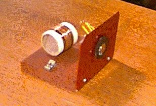
Here is one of mine:
While you are winding the 100 turn coil, go ahead and put a tap in it, say at 30 turns or so. Then you can use the trap for a crystal set as well by adding a detector and earphones across the 30 turns. This lets you do at least two things: 1. It is a nice little crystal set all by itself. 2. You can operate it as a crystal set alone, listen to it while you adjust the trimmers on the capacitor for best frequency coverage - particularly handy if you use a different size wire, different number of turns, different capacitor or different diameter core. Don't leave out the smaller coil of #22, or whatever you use; I tried this trap without the small coil, and it literally wiped out the whole BC band, no matter what frequency it was tuned to - on the other hand, if this is built to be resonant at the shortwave broadcast freqs, it cuts out a larger portion of the offending band.
More fun; put it in the ground path instead, and it works about the same. Put it before or after the antenna tuner (if you use one) - works about the same. Use it as a crystal set along with the other set, and you can listen to two stations at the same time - no, you can't listen to the same station with both sets if they are in series - the one rig cuts out the other. You can even use a trap to provide power to a small transistor amplifier stage if the trapped signal is large enough.
On the air testing with a dc millivoltmeter across the 47k resistor in my detector circuit (see my testing page) shows a signal reduction on "trapped" stationsof about 6 to 14 dB with the trap. I suppose if you have a real monster in your neighborhood, you can put two traps on it for a double stomp; I couldn't see much advantage to the second trap when I tried this. I have not found the need to use a trap bypass switch when the trap isn't in use; I just shove the tuning cap to the other end of the band, and don't notice a reduction in set sensitivity elsewhere. I also notice that on really strong locals, the difference in signal level of 6 dB or so isn't very noticeable, and tuning the trap "by ear" is a bit difficult. When I tune off the offending station a bit, however, I can see the effect of the trap more readily. I made mine as an outboard unit, but you can just as easily incorporate into your main set, just don't make the coils of the two circuits in line (on the same long axis) with each other or you will mutually couple them, which makes for confusing tuning.
One of the unexpected benefits of a trap, as I found out, is that it can enhance the operation of an otherwise sensitive but not so selective crystal set. Using a trap with slightly modified Radio Shack crystal set, I heard a brand new station coming in from several hundred miles away that was ordinarily masked by a stronger station.
Trapping with the pros: Probably the most effective trap is an inductively coupled one. Here's how to make and use it: Make a coil of the same dimensions as your set's main tuning coil, and parallel it with a variable capacitor, also like the one your set uses. Now, place the new trap coil in line (on the same axis) with the main tuning coil, and, with the set tuned to an offending station, tune the trap capacitor to null the station. You can vary the depth of the null by moving the two coils apart. If your set has a separate antenna tuning circuit, the trap coil should be on the side of the set tuning coil away from the antenna coil. I have one of these and have gotten over 30 dB of fairly sharp signal rejection with it. Be advised; when using an inductively coupled trap, expect some interaction with the tuning coil. Using an inductive trap can give some interesting results you don't get from one placed in the antenna line.
More trap fun: If you have a set using in-line antenna and main tuning coils, inductively coupled to each other, here is something else to do with your inductively coupled trap. When trying to dig out a weak station, get as close to it as you can, then tune the trap for a null. Now, take the trap coil and place it between the antenna and main tuning coils. With some careful tuning, you can often isolate the weak station. The trap is giving you an additional stage of filtering and selectivity, and you are now using "triple" tuning. In this configuration, the trap is now functioning as a transfer circuit. You will notice that best performance is with the coils separated from each other by a coil diameter or so.
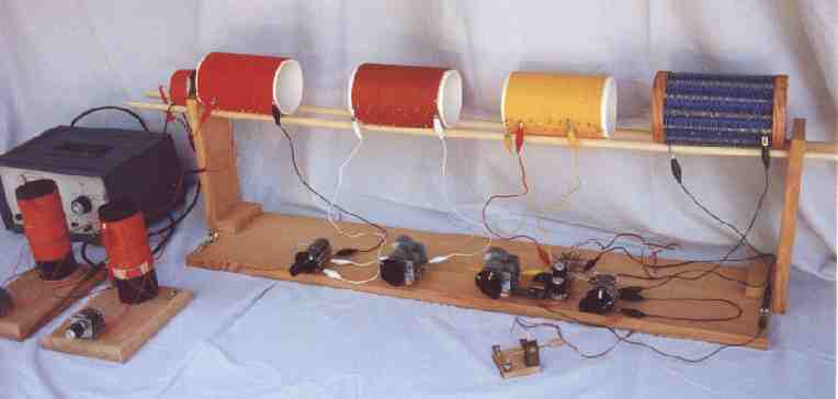
Larry Pizzella also reports good results with in-line traps using largish coils, with the tuned circuit portion of the trap inductively coupled to a separate coil connected to the antenna line which can be moved away from the main trap coil to provide variable coupling. If you look at his big radio, you can see a couple of his outboard traps as well as his inductively coupled trap (the large blue coil on the far right).
I would like to report that trapping my two strong locals opened up the top of the band for me; it didn't completely, but I can now get stations as close as about 20 kHz.
I have been able to successfully trap the HF ghosts somewhat that bedevil me early in the evening, but feel the need to work on this some more. Multiple hf intruders are really tough, but the hf trap I made doesn't use a coupling coil, and is rather broad, so gets a largish portion of the lowest shortwave broadcast band, and supresses a couple of stations sometimes.