There are two basic types of bandspreading: Mechanical and Electrical
Mechanical: The
simplest way to slow your rate of tuning down, or at least let you tune
more sharply, is to use a larger tuning knob; your ability to control your
tuning rate varies directly with the diameter of the knob, assuming you
grab it on the outside edge. Another method that used to be popular
was to have a small diameter shaft turning a larger diameter one connected
to it by a dial cord; the cord was usually kept tight by a small spring.
A third way, still much in use, is to have a planetary dial drive which
makes several rotations to drive the capacitor through one half a rotation.
Dial cord drives are tricky, and planetary drives can cost more than the
rest of the set, so I usually go for the largest knob I can find.
Another thing to watch out for with mechanical
bandspread drives, should you try one, is backlash or slop - you reverse
your direction, and lose a couple of degrees of turn before the capacitor
starts to move. For inductive tuning, usually consisting of moving
a ferrite core in and out of the coil, the once readily available
AM tuning coils used to come with a metal cap through which a screw protruded
that allowed you to vary inductance very slowly using a small knob to twist
the core in an out. Compression capacitors also use a screw to let
you make several turns from stop to stop, but aren't ordinarily used for
main tuning, and are usually for screwdriver use only. If you do
stick a knob on a compression cap with some epoxy, a soda bottle cap should
work, and will allow you about 3 or more revolutions of rotation stop to
stop.
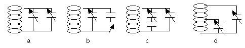
Electrical: Nothing magic about this either. Here you use two or more capacitors to change the amount of capacitance a turn of the knob gives you. Shown below are some of the more common ways to electrically bandspread your tank circuit:
Figure b. is sort of a poor man's bandspread, switching in one or more fixed capacitors to increase capacitance in increments, then adjusting the variable as needed. I used this with my peanut special to get to the bottom of band. The fixed capacitor should be no larger than the range of the variable to prevent skipping over frequencies.
Figure c. has a fixed capacitor in series with one of the variables. This reduces the tuning range of the series variable from about the minimum of the variable to the value of the larger capacitor in the series branch. Good to use if you don't have any small value variables.
Figure d. taps one variable down on the coil, reducing its effect on tuning range. In this case, assuming it is the same value as the band set capacitor for example, its effect capacitance-wise over its full range is approximately equal to the percent of the coil it parallels. If you use a switch to select different coil taps, you can thus vary your bandspread.
A note on using fixed capacitors: I have found that some are better than others, and a lossy one can reduce set sensitivity when the fixed cap is switched in. I have seen this with the readily available ceramic disc capacitors. This may not happen to you, but just be aware of the possibility. You might want to try different types here. Try to use good quality switches as well, and make good solder connections....
Finally, to use the K.I.S.S. principle, use a capacitor with a range no bigger than you need. That is, use only enough range to cover that part of the spectrum in which you are interested. Using a single 365 pF capacitor on the HF bands, one turn of the dial will sweep through several MHz, and no matter how selective your crystal set, you will be sweeping through a lot of dead frequencies and then sweat tuning in and then separating the stations you want to hear.
You can pretty much do with inductors (coils), what you can do with capacitors, and some of the old designs used a lot of variable inductances. Putting inductors in parallel has the same effect as putting capacitors in series, and vice versa for series inductors. My uncle Elmer (I must have had one sometime) told me, however, that circuit Q was highest when you used as much inductance as your frequency range allowed, and to let the capacitor do all the "heavy lifting". Still, some of those old variable inductors look pretty elegant, and I am sure they work pretty well, even if they are a bit more complex to build.