Improve Two-tone, Third Order Testing
First it's important to define the significance of input levels.
Then full details on the measurement technique.
Then full details on the measurement technique.
Two-tone, third-order intermodulation distortion (IM) expresses the degree of non-linearity of an amplifier or mixer. Normally, this parameter is not expressed on data sheets because it is dependent upon operating frequencies, terminating impedance and input levels. So two-tone, third-order distortion must be measured under specific performance conditions.
The two most common errors in these measurements are (1) failure to provide adequate isolation between the two input signal generators and proper impedance matching, and (2) insufficient filtering of the two input test signals. Without adequate isolation and matching, interaction between the test generators and the device-under-test may produce significant errors (as high as 20 dB). Without sufficient filtering, the generator harmonic will contribute to the distortion displayed on the spectrum analyzer and device performance thus will not be properly evaluated.
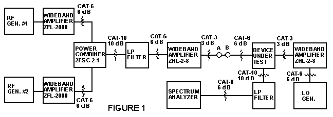
Before proceeding with the actual test, it is very important to note that two-tone, third-order IM distortion is only meaningful when the input levels to the device-under-test are defined. Without these stated input levels, the IM figures have no significance. To illustrate, suppose you wanted a device with a two-tone, third-order level of 60 dB. You could set up the test equipment as shown in the block diagram (Fig. 1) and vary the input levels of generators #1 and #2 until you eventually reached the 60 dB IM level.
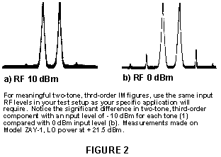
However, unless your particular application dictates exactly the same RF input levels as your test setup inputs, the IM distortion figure is meaningless. For example, examine the spectrum analyzer display for a ZAY 1 double-balanced mixer, Fig. 2. Notice the significant difference in two-tone, third-order component with an input level of 10 dBm for each tone (a) compared with 0 dBm input level for each tone (b).
To repeat a key point, the input level of each signal must be specified before the IM test is begun.
The second key consideration is the need to specify the amount of two-tone, third-order relative to some reference level. The reference level can either be the amount of RF input or desired IF output; the desired IF output reference generally is much more meaningful.
A proper test setup and results are shown in the block diagram, Fig. 1 and Fig. 2.
The two RF input generators are isolated from each other by (1) two wideband (10-2000 MHz) amplifiers, MCL model ZFL-2000; (2) two 6 dB pads, MCL model CAT-6, and (3) a power combiner, MCL model ZFSC-2-2. This combination provides about 70 dB of isolation between the two RF input signals to the power combiner. Mismatch and generator interaction are considerably reduced by this arrangement.
Mini-Circuits offers a wide variety of low-cost fixed attenuators with various connectors (type N,
TNC, BNC and SMA), 1 to 40 dB from DC to 1500 MHz.

A proper test setup for measuring two-tone, third-order IM distortion is shown.
Note the use of two amplifiers and 6 dB pads for input generator isolation and proper 50 ohm
matching. A practice of simply using a Tee-connector between generators develops
mismatches and procedures undesired harmonics which dramatically affect accuracy.
A low-pass filter follows the pads to remove generator second-order harmonics since levels as low as 60 dB can upset the two-tone, third-order measurement.
If the harmonics are not well-filtered, the true measurement figure may be degraded by as much as 20 dB. Here's why. Assume one of the generators has a second-harmonic content. When both RF generator inputs are applied to the mixer, the mixer will generate second-harmonic output. Now if the second-harmonic from the RF generators is 180 degrees out-of-phase with the mixer's second-harmonic, they may cancel causing the two-tone, third-order product to be drastically reduced. The numbers from such a measurement would look very good but could pose a serious error for engineers using the results as a basis for systems design. On the other hand, if both second harmonic signals are in phase, they would add and may increase the two-tone, third-order product by 3 dB. Therefore, without filtering the harmonics of the two-tone RF input, there is good likelihood of obtaining inaccurate results.
A wideband amplifier is now required to increase the level of the two-tone signal so that the two-tone, third-order components can be adequately observed and read on the spectrum analyzer display. Performance of this wideband amplifier is critical since it must not introduce its own third-order components. Pads are included at the input and output of the amplifier to maintain a well-matched 50-ohm system. The two pads following the amplifier allows the device-under-test to be checked at two input levels to verify that the spectrum analyzer is not contributing errors due to its harmonic content (more on this point later).
For high-level mixers, a second wideband amplifier is included between the local oscillator (LO)
and the device-under-test. This additional gain permits an LO level as high as + 17 dBm to be
applied even with the 10 dB isolation pad.

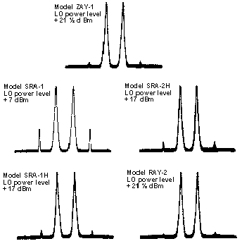
typical intermodulation performance
comparing different level double-balanced mixers
power level each tone = 0 dBm
power level each tone = -10 dBm 

To proceed with the two-tone, third-order IM measurement, first set the power input from each
RF generator. To set the desired power for each signal or tone at the input to the device under
test, first measure the power from RF GEN #1. Thus, disconnect RF GEN #2, replace with a
50-ohm pad to maintain proper matching. Adjust the level of RF GEN #1 until the desired power
at C (Fig. 1) is obtained. To set the power level of RF GEN #2 repeat the procedure.
Next, place the spectrum analyzer after the filter and check the integrity of the setup; no second- or third-order components should be observed. If some level is observed, recheck to eliminate this component. Next, place the spectrum analyzer after the wideband amplifier. Again, no second- or third-order component should be seen on the spectrum analyzer display. If the input signal to the device-under-test has to be reduced, apply attenuation before, rather than after, the wideband amplifier in order to reduce its input level and thus the degree of amplifier distortion. The pads at all three input terminals to the mixer-under-test provide a constant 50-ohm impedance over a broad band to avoid reflections due to mismatch.
Now to check that the spectrum analyzer is not contributing to the distortion figures. If the input to the mixer-under-test is changed 3 dB, a 9 dB change in distortion product should be observed on the spectrum analyzer. The reason: The output of a double balanced mixer is proportional to the cube of the input. If two equal-amplitude signals (EA=EB) are applied, the output would be (EA)³. Thus, if input EA is changed by 3 dB, the output should change by 9 dB.
Suppose this 3:1 change is not observed? The problem could be with the test setup or the linearity of the spectrum analyzer. That's easily determined in this manner. Add 10 dB attenuation between the IF output of the mixer and the spectrum analyzer and repeat the measurement with a 3 dB change again. If the change in IM product is 9 dB, the spectrum analyzer is responsible for introducing distortion. If, on the other hand, less than a 9 dB change is noted, the test setup is at fault. Go back to the input generators and recheck that they are not interacting.
If it is difficult or impossible to observe the intermodulation distortion (IM) output, either obtain a different spectrum analyzer or use a higher level input signal and interpolate the results based on the 3:1 change on IM relationship. For ultra-low distortion mixers, this approach may be the most practical possible.
Upgrade your test setups and system's designs with Mini-Circuits' full line of low-cost, high-performance RF signal-processing components.