Constant-Impedance IF Bandpass Filters Improve Circuits Performance

1. The mixer conversionloss measurement setup is diagramed.
The effect of constant-impedance bandpass filters on conversion loss and intermodulation of mixers is described.
Double-balanced mixers are normally very wideband. When used as down converters, the sum and difference frequencies are of equal amplitude. Filtering is essential to remove the sum frequency.
Conversion loss is usually measured with a l0-dB attenuator at the I-port, followed by a low-pass or bandpass filter to reject the sum frequency (Fig). In this setup, the sum frequency is rejected by the low-pass filter and reflected back into the mixer.
Because of the 10-dB pad, the level of the sum frequency reflected back into the mixer is at least 20-dB below that leaving the I-port. The purpose of the l0-dB pad at the I-port is to provide a 50-Ohm termination at the I-port over a wide frequency range and to prevent the reflected sum frequency from generating secondary IF signals.
In practical systems, attenuation at the IF port is not tolerable, since it decreases the signal level
and increases the noise figure. Instead, a filter is added directly at the I- port to prevent the sum
and intermodulation products from entering the IF amplifier (fig.2)

2. A practical mixer termination is shown.
The output at the I-port consists of fl = ± (fL - fR), the difference frequency, and fS = fL + fR, the sum frequency. The sum frequency is reflected back into the mixer, recombines with the second harmonic of the LO signal and produces fl' = ±[2fL - (fL + fR)], a secondary IF signal that is at the same frequency as the IF.
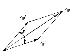
If VIF' and VIF" are the voltage levels caused by IF and secondary IF and ø the phase angle
between them, then VIF is the resultant IF voltage output, which is the vectorial sum of the two
IF voltages (Fig.3).

3. A vector diagram of IF voltage is presented.
When the IF frequency is held constant, and RF and LO frequencies are swept, then VIF', VIF", and ø all vary with frequency. The resultant IF voltage will vary not only because of conversion-loss variation with frequency, but also because of variation of ø. This could result in undesirable ripples in the conversion-loss response. Figure 4 shows the effect when a commercial mixer such as Mini-Circuits' ZFM-1H is followed by a low-pass filter, MCL BLP-50. As much as 3dB ripple in conversion-loss response can be seen.
If the impedance at the I-port is held constant over a wide frequency range and the sum
frequency is prevented from reentering the mixer, flat conversion loss can be realized.

4. Conversion loss is shown as a function of the IF filter.
Constant-Impedance Filters
Mini-Circuits has introduced a series of constant-impedance filters for different IF frequency
ranges. These filters are a bandpass design with typically 1dB bandwidths of 30 percent. Stop-band return loss is l8-dB (typical), up to l0 times the IF center frequency. Insertion loss and
return loss of a model PIF-40 IF filter with 40-MHz center frequency is shown in Figure 5.

5. Insertion loss and return loss of a model PIF-40 IF filter are plotted.
If the I-port of a mixer is terminated with a constant-impedance filter (Fig. 6) such as the PIF-40 the filter attenuates the sum frequency by absorption. In Figure 4, the frequencies are:
RF = 80 to 500 MHz
LO = l20 to 540 MHz
If = 40 MHz
Sum = 200 to 1040 MHz
When the PIF-40 is used at the IF output, the sum frequency is attenuated by at least l4 dB. Also,
the return

6. A mixer is diagrammed with the constant-impedance filter at IF.
loss is l3 dB up to l040 MHz. The level of sum signal reflected into the mixer is determined by the return loss of the filter. Figure 4 shows how flat the conversion loss is as a function of frequency, which is within 0.3dB p-p up to 500 MHz, a substantial improvement form 3dB p-p when the BLP-50 is used at the output.
Constant-impedance filters are bandpass in nature; hence, signals outside the passband are
attenuated. The LO and RF signals (which fall outside the passband) are attenuated, and isolation
is improved.
Effect of IF Termination on Intermodulalation
When the IF is terminated with conventional low-pass or bandpass filters, the sum frequency is
reflected and reenters the mixer. This influences conversion loss. When more than one carrier is
present at the input, the most serious intermodulation of concern is the two-tone, third-order
intermodulatiom. This is because intemnodulation frequencies are separated from the IF
frequency by the same spacing as that of the RF carriers. Mathematically, the intermodulation
frequencies are
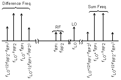
fLO ± (2f RFI - fRF2)
and fLO ± (2fRF2 - fRF1)

7. The mixer out put spectrum is presented.
Figure 7 shows the frequency spectrum at the IF with two IF signals. If the sum-frequency components are reflected back into the mixer, they combine with the second harmonic of the LO and produce the desired IF frequencies and associated intermodulations. The primary and secondary IF products add vectorially and affect the intermodulation level with reference to the IF output. With a constantimpedance filter at the IF, the sum products are absorbed and the intermodulations are not affected.
Besides the two-tone, third-order problem, the reflected signals mix with LO signals and generate secondary intermodulation products. Constant-impedance filters will minimize these effects and provide the ideal termination.