LZY-1
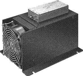
ULTRA-LINEAR RF AMPLIFIER 20 MHz - 512 MHz
25 WATTS MIN., 1 dB COMPRESSION
(50 WATTS TYP., MAX. OUTPUT)
TABLE OF CONTENTS
1.0 General Description
2.0 Electrical Performance Specifications
3.0 Mechanical Specifications
4.0 Electrical Features
4.1 Overdrive Protection
4.2 Thermal Overload Protection
4.3 Reverse Polarity Protection
4.4 Transient Protection
4.5 Shut-off Terminal
5.0 Mechanical Features
5.1 Mechanical Outline
5.2 Heat Sink
5.3 Cooling Fan
5.4 Weight
6.0 Suggested Applications
6.1 AM Amplification
6.2 FM Amplification
6.3 Linear Pulse Amplification
6.4 Multi-Carrier Amplification
6.5 Television Carrier Amplification
6.6 Broadband 20 MHz - 512 MHz Swept Signal
6.7 Feedforward Amplification
7.0 Alternative Heat Sinking / Cooking
8.0 Quality Assurance Prvisions
8.1 Acceptance Test Procedure
8.1.1 Acceptance Test Procedure Test Setup
8.1.2 Test Equipment List
8.2 Warranty
9.0 References
LIST OF ILLUSTRATIONS
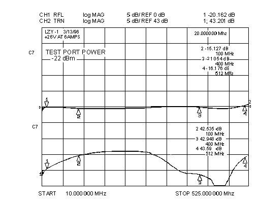
Figure:1 Small Signal Response @ -22 dBm Pin
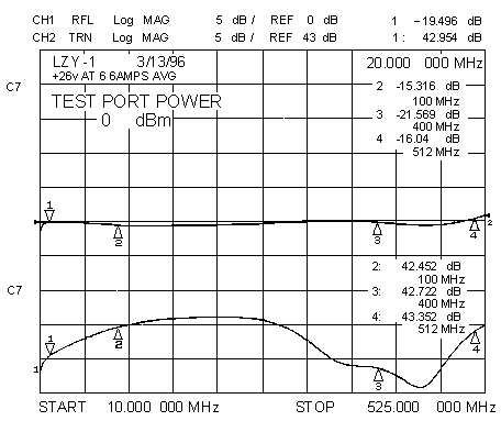
Figure:2 Large Signal Response @ 0 dBm Pin
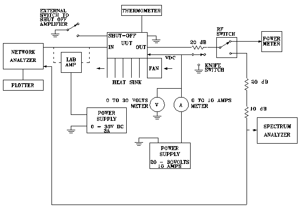
Figure:3 Acceptance Test Procedure Test Setup
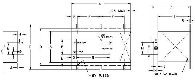
Figure:4 Mechanical Outline Drawing
LIST OF TABLES
Table:1 Electrical Performance Specifications
Table:2 List of Test Equipment
1.0 GENERAL DESCRIPTION
The LZY-1 is a low cost, rugged, versatile, 43 dB Typ. gain, broadband, Class A Linear RF Power Amplifier Module designed to operate linearly over the 20 MHz to 512 MHz frequency band. The LZY-1 features low compression and low harmonic distortion at 25 watts, which make it ideally suited to a wide variety of applications.
The conservative electrical and thermal design and careful attention to semiconductor ratings insures continued years of service in both the laboratory and many commercial and semi-hostile military environments.
The workmanship, quality, and attention to protective features along with selection of components to COTS (commercial off-the-shelf) guidelines, further enhance applicability and long MTTF.
The unit electrical performance is specified at +26 VDC but will operate without damage over the +22 VDC to +30 VDC range.
The LZY-1 is supplied with its own high thermal efficiency heat sink and ball bearing cooling fan for immediate use and reliable operation.
For applications where the heat sink / fan assembly presents a difficult physical fit, the RF linear amplifier module may be removed and operated safely with alternative heat sink / cooling methods if the guidelines in paragraph 7.0 are followed. Operation of the amplifier module without proper heat sinking is not recommended and violates the warranty.
Protective features such as Input Overdrive, Reverse Polarity, Transient Protection and Thermal Overload with automatic reset are included. A separate shut-off terminal is provided for remote amplifier on/off control.
The LZY-1 was designed to satisfy a range of broad, and narrow-band multitone or single frequency applications for original equipment, production test and laboratory equipment uses.
2.0 ELECTRICAL PERFORMANCE SPECIFICATIONS
The Electrical Performance Specifications and limits are listed in Table 1.
Typical broadband small and large signal gain and return loss responses are shown in Figures 1 and 2.
Comparison of the curves and gain data at the measurement points illustrates the dynamic linearity of the LZY-1 across the frequency range.
