
At the time of writing this article, I have not produced a kit for and HF project. This has been due to the inability of other people to duplicate coil-winding data. It is a fact that if 10 different people wind a coil according to the same instruction, you will have 10 different coils. I have also received endless e-mail messages asking for further clarification of the coils I use in my projects. Wire thickness, insulation material, turns spacing, and even temperature have been requested. No-one has yet asked me for the mood, thinking processes or patience of the winder, but these have a far greater impact upon the final coil produced.
Now I have found a solution. Etch the coils on a PCB. I have been doing this for a number of years with VHF circuits (see my FM microphones) but I have recently done experimented with coils of a higher inductance. Of course, this now requires a multi-layer PCB. So here is what i did:
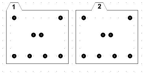
I fitted wires to the receiver PCB so that there was about 3cm of wire sticking up from the board on the component side of the PCB. Onto these I fitted in turn, four boards, each with a spiral coil. The receiver PCB must have the same coil pin spacing and all coil PCBs must be made from the same template. Here is the blank template I used:

The pads and their spacing can then be copied to the main project PCB for perfect spacing of the wires. To each of the above PCB I added a spiral track to form the inductor. Note that alternate boards must have the spiral in the opposite direction. Because there are three centre transition-pads, there can be a maximum of 6-layers with this example, but you can add many more, as you see fit. If you use my PCB tracks and pads (see the DOWNLOAD section) to create PCB's then the scale of this project will fit nicely. Here is an example of the first prototype PCB coil foil pattern, but here I have only shown two of the four layers:

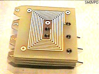
Each board is 35mm x 40mm (excluding the order tabs) and has sufficient room for 9-turns. With the design above I achieved 4-layers, each having an inductance of 5uH. the four layers therefore gave me 20uH so they can be brought to resonance at 4MHz with just 150pf. With four layers I also had three tapping points, 25%, 50% and 75% of the coil, all of which can be accessed on the project from any direction board without links or tracks crossing. Here is a photograph of the first prototype PCB coil. I built four of them and all were within 1% of each other's inductance. I will put the PCB foil patterns into the DOWNLOAD section of my homepage as soon as I have the time.

I see no reason why the coil assembly cannot have the wire leads projecting from both sides of the boards and the coil then mounted verticall on the PCB. If you want to be really clever then you could have plug-in coils with the in-built padding capacitors for tuning. I will now go back to the workbench and create an HF project using this technique so that everyone can build HF projects and get the coils right, first time, every time.

I hope that you have fun with this technique, 73s from HARRY, Lunda, Sweden.
Return to INFO page