THE ELECTRIC WAVE![]()
BALUNS AND COAXIAL AERIALS
 If you are dealing with radiofrequency aerials you might like to experiment with
the configurations proposed. In fig. 1 there is a balun which transforms an unbalanced
line into a balanced feed. You need to connect a variable capacitor, typically a trimmer
capacitor, between two points on the braid of the terminal part of the coaxial cable as
shown in the drawing. The length and the capacitor value are optimized for operation in
the Citizen Band and 50W cable but the set up is not critical at all and should work at
other frequencies as well. The advantage of this balun is that you can provide a perfectly
balanced feed to the aerial thus compensating for any unbalance introduced by the
topography of the ground around the same aerial. Another interesting application for this
balun is to use it as a power splitter: if you measure the output power relative to ground
(i.e. the cold side of the capacitor), you may adjust the power fed to the two terminals
by simply operating on the capacitor. The phase relationship has not been investigated.
Fig. 2 is a more classical approach to the problem: two quarter wavelength sections of the
same coaxial cable give a balanced output with the least of trouble, but it must be
mentioned that it works well only around the designed frequency, it is not a wideband
balun. Length l is
equal to (l/4)xP where l is the operating wavelength and P is the
propagation factor which depends on the type of dielectric material used in the coaxial
cable as shown in the table:
If you are dealing with radiofrequency aerials you might like to experiment with
the configurations proposed. In fig. 1 there is a balun which transforms an unbalanced
line into a balanced feed. You need to connect a variable capacitor, typically a trimmer
capacitor, between two points on the braid of the terminal part of the coaxial cable as
shown in the drawing. The length and the capacitor value are optimized for operation in
the Citizen Band and 50W cable but the set up is not critical at all and should work at
other frequencies as well. The advantage of this balun is that you can provide a perfectly
balanced feed to the aerial thus compensating for any unbalance introduced by the
topography of the ground around the same aerial. Another interesting application for this
balun is to use it as a power splitter: if you measure the output power relative to ground
(i.e. the cold side of the capacitor), you may adjust the power fed to the two terminals
by simply operating on the capacitor. The phase relationship has not been investigated.
Fig. 2 is a more classical approach to the problem: two quarter wavelength sections of the
same coaxial cable give a balanced output with the least of trouble, but it must be
mentioned that it works well only around the designed frequency, it is not a wideband
balun. Length l is
equal to (l/4)xP where l is the operating wavelength and P is the
propagation factor which depends on the type of dielectric material used in the coaxial
cable as shown in the table:
Dielectric |
P |
Typical Cable |
Solid polyethylene |
0.665 |
RG 58 / RG 11 |
Polyethylene/air |
0.835 |
RG 62 / RG 79 |
Fluorocarbon (Teflon) |
0.675 |
RG 94 / RG 209 |
Foam polyethylene |
0.816 |
TV cable |
 The balun in fig. 2 can be wired also as in fig. 3. In fact, points A and B are at
the same potential and can be connected together. Nothing changes from the electrical
point of view but it can make a more compact construction in certain circumstances. The
first application will allow you to install a CB car aerial in any other place without the
need of the metal body of the car (fig. 4). The vertical section of the coaxial cable is
short-circuited at the lower end. You might need to adjust the length of the whip, once in
its final place, because distance d is to be subtracted from the total length of
the car aerial.
The balun in fig. 2 can be wired also as in fig. 3. In fact, points A and B are at
the same potential and can be connected together. Nothing changes from the electrical
point of view but it can make a more compact construction in certain circumstances. The
first application will allow you to install a CB car aerial in any other place without the
need of the metal body of the car (fig. 4). The vertical section of the coaxial cable is
short-circuited at the lower end. You might need to adjust the length of the whip, once in
its final place, because distance d is to be subtracted from the total length of
the car aerial.
The typical application is shown in fig. 5. Two different lengths are given: one applies to 50W cables and baluns and the other applies to 75W cables and baluns (fig. 7), these values are good for the design of receiving FM or TV aerials right up to UHF. It must be said that these designs are narrow band aerials and are not suitable to cover a wide frequency range. This means that if you tune to a specific TV channel you will get a performance that could be better than a Yagi but gives poor results at other channels. One way around is to purposefully mismatch the design in order to cover a wider range but I was unable to assess how good this solution was.
 If you
find that the aerial is too long at the working frequency, you could apply the design of
fig. 6 where a coil is inserted at the base of the aerial. The coil is made with 17 turns
of 2mm electric wire on a 17mm form. These data are valid for the 27Mhz band and must be
properly scaled at other frequencies. In all cases the vertical coax must be shorted at
the far end because it works also as an impedance matcher for the rest of the aerial.
Installation can be vertical, as shown in the drawings, or horizontal.
If you
find that the aerial is too long at the working frequency, you could apply the design of
fig. 6 where a coil is inserted at the base of the aerial. The coil is made with 17 turns
of 2mm electric wire on a 17mm form. These data are valid for the 27Mhz band and must be
properly scaled at other frequencies. In all cases the vertical coax must be shorted at
the far end because it works also as an impedance matcher for the rest of the aerial.
Installation can be vertical, as shown in the drawings, or horizontal.
 All the mentioned aerials were
tested in the 27Mhz band with satisfactory results: best performance being from the design
of fig. 5. Gain was measured between 6 and 9 dB but the instrument available was not very
accurate and I cannot bet on the number reported. As a receiving aerial it was tested in
the FM range, VHF and UHF: in the VHF range I could see a TV channel that I was unable to
see with a 4 element Yagi; in the UHF range the mechanical construction is rather critical
due to the small size and the need of a wideband aerial becomes a major drawback.
All the mentioned aerials were
tested in the 27Mhz band with satisfactory results: best performance being from the design
of fig. 5. Gain was measured between 6 and 9 dB but the instrument available was not very
accurate and I cannot bet on the number reported. As a receiving aerial it was tested in
the FM range, VHF and UHF: in the VHF range I could see a TV channel that I was unable to
see with a 4 element Yagi; in the UHF range the mechanical construction is rather critical
due to the small size and the need of a wideband aerial becomes a major drawback.
SINGLE LED FLASHER
 Flashing a LED should not require a complex circuit. A
reverse biased transistor does the job in a nice way. Circuit "a"
flashes the LED twice a second: changing the capacitor and/or the resistor will change the
frequency, also the supply voltage will influence its frequency of operation. A BC337 can
be used instead of the 2N2222A; in this case the supply voltage can be lowered to 9V.
Circuit "b" gives the same result but it will work directly off
the mains, so be careful with the live wire because it can be a hazard if you do not take
all necessary precautions. If the mains voltage is 110VAC the resistor should be decreased
from 100K to 47K. If a BC337 is used, then the resistor is 390K for a 220V mains and 180K
for a 110V mains. The zener is not required for its operation: it is only a safety measure
that avoids voltage build up if the LED gets disconnected. When you reconnect it, the
current surge will destroy the transistor and the LED. The capacitor could be damaged as
well.
Flashing a LED should not require a complex circuit. A
reverse biased transistor does the job in a nice way. Circuit "a"
flashes the LED twice a second: changing the capacitor and/or the resistor will change the
frequency, also the supply voltage will influence its frequency of operation. A BC337 can
be used instead of the 2N2222A; in this case the supply voltage can be lowered to 9V.
Circuit "b" gives the same result but it will work directly off
the mains, so be careful with the live wire because it can be a hazard if you do not take
all necessary precautions. If the mains voltage is 110VAC the resistor should be decreased
from 100K to 47K. If a BC337 is used, then the resistor is 390K for a 220V mains and 180K
for a 110V mains. The zener is not required for its operation: it is only a safety measure
that avoids voltage build up if the LED gets disconnected. When you reconnect it, the
current surge will destroy the transistor and the LED. The capacitor could be damaged as
well.
LONG DELAY TIMER
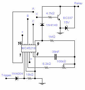 A max. delay of 20 hours is achieved by this relatively simple circuit. A permanent
ground, or no signal, at the trigger input starts the timer. A ground at the relay output
is available after a set time that depends on the connection of the transistor base (X) to
one of the counter output: connection with (C) gives a min. delay of 1m 40s and max. of
18m 30s. Connection with (B) gives a min. delay of 13m 20s and max. of 2h 28m. Connection
with (A) gives a min. delay of 1h 47m and max. of 20h. Supply voltage is between 6 and 15V
and longer delay could be obtained by increasing the capacitor value up to 10 times with a
delay in excess of 1 week. A positive at the trigger input will reset the counter. Adjust
the 100K pot. for the desired timing. The load is typically a relay but any load with a
max. current of 200 mA will work fine. Admittedly this is not a very original circuit but
can save some time if you need to build one.
A max. delay of 20 hours is achieved by this relatively simple circuit. A permanent
ground, or no signal, at the trigger input starts the timer. A ground at the relay output
is available after a set time that depends on the connection of the transistor base (X) to
one of the counter output: connection with (C) gives a min. delay of 1m 40s and max. of
18m 30s. Connection with (B) gives a min. delay of 13m 20s and max. of 2h 28m. Connection
with (A) gives a min. delay of 1h 47m and max. of 20h. Supply voltage is between 6 and 15V
and longer delay could be obtained by increasing the capacitor value up to 10 times with a
delay in excess of 1 week. A positive at the trigger input will reset the counter. Adjust
the 100K pot. for the desired timing. The load is typically a relay but any load with a
max. current of 200 mA will work fine. Admittedly this is not a very original circuit but
can save some time if you need to build one.
MAINS FREQUENCY METER
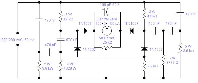 Mains
frequency is pretty stable and it is unlikely that you have to measure it but if
you have an emergency generator you might find this circuit useful as it will
give an indication whether the generator is running too fast or too slow.
Actually you can use the mains frequency to calibrate it by adjusting the 25K
multiturn trimmer until it reads 0. The odd looking components values are easily obtained
using standard values: 3777 is 3900 in parallel with 120KW, 4020 is 3900 and
120 in series, 570nF is 470 with 100nF in parallel and 400nF is 4 x 100nF
capacitors in parallel. Components should be chosen for their stability and
precision. 1% tolerance would be ideal but 5% is acceptable so long as you
measure them with a good meter. Capacitors should be properly rated for direct
connection to the mains and resistors should have a low temperature coefficient
as it will adversely affect the zero setting and change the filters response.
The 100mF capacitor could be
occasionally reverse biased with a voltage of 0.1-0.2 V. There is no problem for
the capacitor which is generously rated. Operation is quite
simple: connect it first to the mains, wait about 4-5 minutes until all
resistors reach their working temperature, calibrate, and then connect to the
generator. Variation in the mains voltage will not change
the zero setting but will make the meter more or less sensitive: for
example, a reading of 51 Hz will show as 51.1 with a 10% supply voltage increase.
Mains
frequency is pretty stable and it is unlikely that you have to measure it but if
you have an emergency generator you might find this circuit useful as it will
give an indication whether the generator is running too fast or too slow.
Actually you can use the mains frequency to calibrate it by adjusting the 25K
multiturn trimmer until it reads 0. The odd looking components values are easily obtained
using standard values: 3777 is 3900 in parallel with 120KW, 4020 is 3900 and
120 in series, 570nF is 470 with 100nF in parallel and 400nF is 4 x 100nF
capacitors in parallel. Components should be chosen for their stability and
precision. 1% tolerance would be ideal but 5% is acceptable so long as you
measure them with a good meter. Capacitors should be properly rated for direct
connection to the mains and resistors should have a low temperature coefficient
as it will adversely affect the zero setting and change the filters response.
The 100mF capacitor could be
occasionally reverse biased with a voltage of 0.1-0.2 V. There is no problem for
the capacitor which is generously rated. Operation is quite
simple: connect it first to the mains, wait about 4-5 minutes until all
resistors reach their working temperature, calibrate, and then connect to the
generator. Variation in the mains voltage will not change
the zero setting but will make the meter more or less sensitive: for
example, a reading of 51 Hz will show as 51.1 with a 10% supply voltage increase.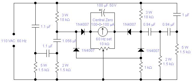 Full scale deflection is
around +/- 2 Hz. If you wish to accommodate a wider range of +/- 3.5 Hz, typical
for a petrol driven generator, you have to change the 2.2KW resistor to
12KW.
Full scale deflection is
around +/- 2 Hz. If you wish to accommodate a wider range of +/- 3.5 Hz, typical
for a petrol driven generator, you have to change the 2.2KW resistor to
12KW.
WARNING! This circuit is directly connected to the mains and should be assembled in a box which will avoid access to any of its part and care must be exercised when calibrating the unit. If you live in the States or you have a 110 VAC, 60 Hz mains, you may try the second circuit: the reported values are calculated values, I did not actually test the unit. The odd capacitors values are easily obtained with the combination of standard values: 0.94 is 2 x 0.47 in parallel, 1.056 is 1mF + 56nF in parallel and 1.1 is 1 + 0.1mF.
ELECTRONIC RELAY
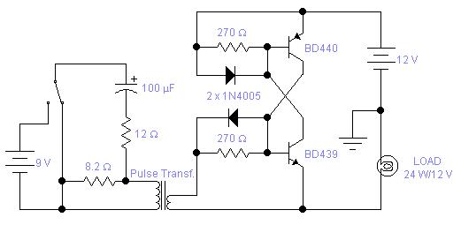 In
some applications where you require speed of operation and no contact
bouncing, you may find this circuit helpful. The medium power complementary pair
will switch on and off a load up
to 3A. You may modify the
circuit to carry up to 10A using suitable power transistors and diodes. The left
side of the circuit shows a typical drive. This electronic relay will latch in the on or
off position depending on the direction of the pulse going through the primary
winding of the transformer. You may omit the capacitor altogether; in this case
the circuit behaves very much like the coil of a relay: when you apply a voltage
to the primary it will switch on and when you remove the voltage it will switch
off. The drawback in this second case is that there is a large amount of power
dissipated in the 12W resistor which must be rated
accordingly. The pulse transformer is recovered from a faulty electronic neon
light. The drive circuit for these lamps always includes a pulse transformer.
The higher impedance, or resistance, is the primary and the other winding is the
secondary. The measured resistance was below 0.4W and
the inductance was 680 and 47mH for the primary and
secondary respectively. The ideal would be a pulse transformer with two secondary windings so
that both transistors could be driven but you have the same
results if the drive is applied to one transistor only. The circuit has its limitations: there is a voltage drop
across the switch, in the on state, between 0.7 and 1V, this may not be
acceptable in low voltage applications; it will work only with DC supplies and
there is a minimum sustain current, 12mA in the circuit shown. Below this
current the switch will revert to its off state. You may, of course, design a
circuit with low power transistors with a sustain current of only a few mA
if necessary.
In
some applications where you require speed of operation and no contact
bouncing, you may find this circuit helpful. The medium power complementary pair
will switch on and off a load up
to 3A. You may modify the
circuit to carry up to 10A using suitable power transistors and diodes. The left
side of the circuit shows a typical drive. This electronic relay will latch in the on or
off position depending on the direction of the pulse going through the primary
winding of the transformer. You may omit the capacitor altogether; in this case
the circuit behaves very much like the coil of a relay: when you apply a voltage
to the primary it will switch on and when you remove the voltage it will switch
off. The drawback in this second case is that there is a large amount of power
dissipated in the 12W resistor which must be rated
accordingly. The pulse transformer is recovered from a faulty electronic neon
light. The drive circuit for these lamps always includes a pulse transformer.
The higher impedance, or resistance, is the primary and the other winding is the
secondary. The measured resistance was below 0.4W and
the inductance was 680 and 47mH for the primary and
secondary respectively. The ideal would be a pulse transformer with two secondary windings so
that both transistors could be driven but you have the same
results if the drive is applied to one transistor only. The circuit has its limitations: there is a voltage drop
across the switch, in the on state, between 0.7 and 1V, this may not be
acceptable in low voltage applications; it will work only with DC supplies and
there is a minimum sustain current, 12mA in the circuit shown. Below this
current the switch will revert to its off state. You may, of course, design a
circuit with low power transistors with a sustain current of only a few mA
if necessary.
 In
order to generate a single note you may try these simple circuits. With only
three components you may implement some basic buzzers. You need a telephone
earpiece for the first circuit. Any old telephone set has got one of those
magnetic earpiece that is right for our purposes. Add an extra capacitor and a
transistor and you have your buzzer. Frequency of operation is about 1800 Hz and
the capacitor must be changed if you wish to have a different frequency. The
second circuit is implemented with a ceramic sounder: its intrinsic capacity is
used to make another simple buzzer. Working frequency is 800 Hz and power drain
is really low. The operating voltage is 9,5 - 20V for the circuit with the
ceramic sounder and 8 - 16V for the other circuit. Do not expect a loud sound
level: it is rather limited just as the current drain is. These buzzers are
suitable for audio signaling on portable devices and wherever it is necessary to
have a sound source implemented with a minimum components count. Not all
transistors will oscillate: you have to use the specified type although I found
that the BC109 and 2N2222A will also work albeit at a slightly different
voltage.
In
order to generate a single note you may try these simple circuits. With only
three components you may implement some basic buzzers. You need a telephone
earpiece for the first circuit. Any old telephone set has got one of those
magnetic earpiece that is right for our purposes. Add an extra capacitor and a
transistor and you have your buzzer. Frequency of operation is about 1800 Hz and
the capacitor must be changed if you wish to have a different frequency. The
second circuit is implemented with a ceramic sounder: its intrinsic capacity is
used to make another simple buzzer. Working frequency is 800 Hz and power drain
is really low. The operating voltage is 9,5 - 20V for the circuit with the
ceramic sounder and 8 - 16V for the other circuit. Do not expect a loud sound
level: it is rather limited just as the current drain is. These buzzers are
suitable for audio signaling on portable devices and wherever it is necessary to
have a sound source implemented with a minimum components count. Not all
transistors will oscillate: you have to use the specified type although I found
that the BC109 and 2N2222A will also work albeit at a slightly different
voltage.
![]() Eager
for more
Eager
for more
 Full astern to main
page
Full astern to main
page
![]()
