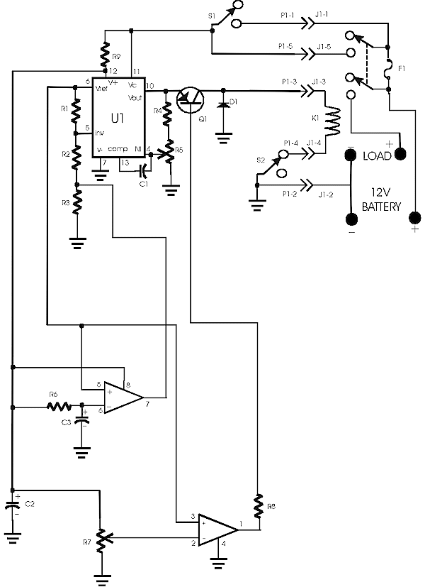
Description: 12 Volt DC Load Control and Battery Protection
The purpose of this
circuit is to be able to remotely connect a 30A load to a 12 volt battery and to
automatically disconnect the load if the battery becomes discharged to the battery cutoff
voltage(approximately 11.5 volts). A 30 amp contact relay was chosen as tests conclude
that the power lost with the relay and the relay drive circuits was less than with a power
mosfet.
For example if the
power mosfet has an on resistance of .02 ohms the power loss at 30 Amps would be .02 X
900=18W. Measurements showed that the contact resistance of the relay was .003 ohms. Using
the same formula for power, .003 X 900=2.7W. The power consumed by the relay driver
circuit is very close to .055 amps (55Ma).
Circuit
operation
With the circuit
energized, pressing S1 apples 12V to the coil of K1. One set of contact of K1 parallels
the contacts of S1 keeping the relay energized. The other set of relay contacts supplies
power to the load. As soon as S1 is depressed, C3 starts to charge through R6. When the
voltage across C3 reaches the reference voltage of U1(approximately 7.0V), U2B (open
collector) goes low. This shorts R3 and reduces the relay coil voltage to approximately
6V. This is the continuous coil voltage for K1. Trimpot R5 adjusts this voltage. When the
applied voltage decreases to approximately 11.5 volts, U2A (open collector) goes high and
turns off Q1, which causes K1 to deenergize. This trip voltage is adjusted by R7.
Depressing S2 (normally closed deenergizes the coil of K1 removing the power to the load
and the relay drive circuit.
Parts List

Amplifying comments
By reducing the coil
voltage on the relay K1 the current consumed is reduced to 1/2 normal. The relay will
still function normally on reduced voltage once energized at near full voltage. Adjustment
of R5 and R7 is accomplished by the use of an adjustable power supply. Ensuring that the
load and the 12V battery are disconnected. Adjust the power supply to approximately
13 V. Connect the power supply to the 12V battery terminals of the circuit. Press S1.
After about 2 seconds measure the voltage on the relay coil. Adjust R5 for 6V on the relay
coil. Measure the voltage between pin 3 of U2A and ground. Adjust the power supply to
11.5V and adjust the voltage between pin 2 and ground of U2A with R7 to be the same
voltage as the voltage on pin 3 and ground of U2A. The relay and the fuse are
mounted in a enclosure near the battery. The control circuit is in it’s own enclosure
in a convienent location. The connecting cable is of 22 guage wire, as the maximum current
in any wire is very close to 100 Ma.
|