|
Circuit Archives
Measurement & Control Circuits/ Closed Loop
|
|
Pulse Width Modulator
Reprinted with permission
from Rudolf Graf.
For this and over 1000 other electronic circuits, review and order Rudolf
Graf's Encyclopedia of Electronic Circuits on CD-ROM Vol-1
McGraw-Hill ISBN0078528119


FD52-8 |
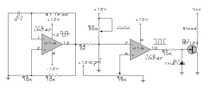
Description:
This circuit allows
the effective power in a load to be controlled by varying the duty cycle of the on/off
ratio of load current. No power is dissipated in the switching circuit. U1A generates a
bipolar square wave that is integrated into a triangle by R4 and C2. Reference voltage
from R6 is fed to a comparator. The triangle wave on C2 goes to the comparator as well. By
varying the reference voltage (R6), the output waveform is a variable width pulse, that
drives Q1. R6 controls on/off ratio and therefore load power. R5 sets the offset of the
triangle wave across C2. (Reprinted with permission from Popular Electronics, 2/91, p. 28.
Copyright Gernsback Publications, Inc., 1991.) From figure FD52-8 of Encyclopedia of
Electronic Circuits on CD-ROM Vol. 1.
|
|

