[Home Page] [References & Links]
Long before I was born, someone came up with a simple cheap adapter that would convert just about any oscilloscope into a component tester. The adapter causes a component's current vs. voltage characteristics to be displayed on an oscilloscope's screen. The name "Octopus" presumably came from either it's popularity in the US Navy or by virtue of all the wires connecting with the device.
Links & references about these testers are listed here.
The classic version of The Octopus consists of only a filament transformer and three resistors.
 Changes I made:
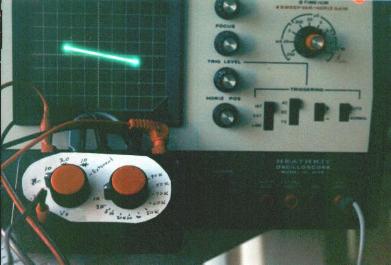
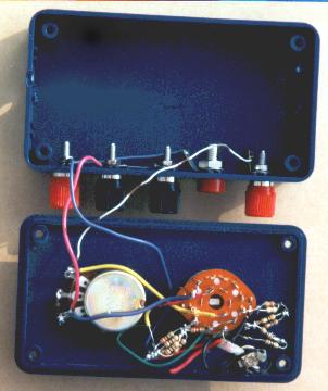
Rather than using a conventional transformer for the signal source, I used an old wall wart. It was originally
made for an early TI calculator and was rated at 3.3 VAC. My voltmeter shows an output of 7.8 VAC under
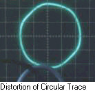
light loading. One thing I've noticed is that when viewing a capacitor signature with a circular shape, the
circle is rather lumpy ( 0.1uF capacitor/reference pot at 26k ohms). I think this is due to saturation of the
transformer core. I've heard that it's rather common to design cheap transformers that way.
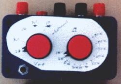
Rather than use a fixed reference resistor such as is used in the schematics I've seen, I used a 1 K resistor in series with a 100k pot. The dial was then calibrated for resistance in ohms. By adjusting the pot for either a 45 Deg. line (for a resistor), or a circular display (for a capacitor), you can read the test part's impedance at 60 Hz under various conditions. Diode D1 is added to one of the 10 volt settings. This position can be used to prevent applying a reverse voltage to polarized capacitors during testing.
Resistors R1 - R4 form a voltage divider to allow selection of 3 different voltage levels for testing. I chose
peak voltages of .3, 3, and 10 (3 volts peak = 6 volts peak-to-peak). The transformer output voltage is 10
volts (peak) or 20 volts (peak to peak). I chose 3 volts because it's high enough to check leds but low
enough so that the maximum current through the test device is about 2 milliamps. The .3 volts is low
enough so that semiconductor devices should not interfere with testing parts in circuits. The output
impedance of the voltage divider limits the minimum value that can be used for the comparison resistor
R5 - R6 without causing a distortion of the oscilloscope trace. The voltage divider on my tester has about
90 ma flowing through it to keep it's output impedance reasonably low.The power dissipated in R1 - R4
needs to be calculated as it is easy to overheat them.
One limitation of the original version of the tester is that at 60 HZ, the range of capacitor, inductor, and ESR values that can be evaluated is rather limited. These ranges can be extended by using a sine wave/ function generator in place of the original transformer/voltage divider. The sixth position of the voltage selection switch on my tester is left unconnected internally. This position allows for an external sine wave source to be connected to the oscilloscope vertical and horizontal input jacks.
If I were constructing another test adapter, I would probably build it into the same case as a function generator and a quick & cheap ESR test adapter. As it is, I built the function generator separately.
Copyright © 2000 by Stephen M. Powell
Comments on this page? E-mail smpowell@taxspam.usa.net
(remove the obvious extra eight character political statement from e-mail address)