Home Page

Introduction Regulators Other Options

Other Options

Before the present family of three-pin IC regulators you had a choice of a few regulators on the market which included the notorious LM723 , a versatile but rather unfriendly IC. There are all kinds of applications, some very complicated and others very simple when using the power transistor as a variable resistor controlled by a low power NPN or PNP transistor reference.

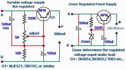
The following two designs are very basic voltage supply controls for a bench supply. The first is a simple variable voltage control that allows you to change voltage from 0V to its maximum. It's easy to build. Choose a power transistor and use a heat sink.

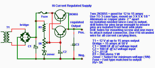
The next circuit is a regulated fixed supply using a zener diode and resistor as the regulating elements connected to the base of the transistor as shown .

The circuit shown below is a combination of an adjustable resistance with a Zener diode which will enable adjustment of a regulated voltage , note that you will not be able to lower the voltage below the zener's voltage value. This type of regulation will allow you to use higher current output than a single regulator IC as described previously which is limited to 1.5A. For still higher current output an additional identical transistor can be connected in parallel.

The next circuit is an adjustable regulated supply circuit which incorporates a control to reduce the ripple to a minimum. It is important to remember that the input voltage may not be more than the IC recommended maximum voltage .

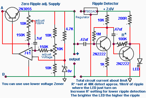
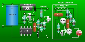
Normally, to adjust the ripple it would be necessary to be able to monitor it with an oscilloscope. But if you don't have a scope then you might want to check out a small circuit I've designed that will monitor the ripple voltage continuously. And then it's a simple matter to add another control on the cabinet so that while observing the LED when the supply is under load, adjustments can be made to control ripple. The ripple detector voltage supply is regulated at 2.6V and will remain stable at all voltage levels above 4V of the transistor ouput.
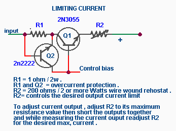
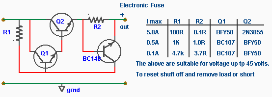
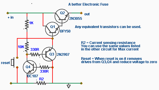
Controlling Current

The simplest way of controlling current is to insert a high wattage resistance in series with the output transistor. A variable rehostat (R2) is very handy for adjusting the maximum current delivered to a circuit. It can be used to check for shorts and excessive current caused by errors or malfuntions as well as prevent damage to the circuit being tested. In the trade it's called a "Smoke Test".

In case of accidental shorting of the ouputs an overcurrent protection provided by R1 and Q2, as shown in the circuit, can be used . Since R1 is in series with the Q1, the voltage across it is proportional to the output current. This voltage is used to drive Q2 so that the larger the output current becomes, the more Q2 turns on. When Q2 comes on the base drive is reduced or removed from Q1 regulation, limiting the output current. For more current output R1 can be reduced . By experimenting with your supply output current you can adjust the resistance value of R1 to achieve your requirements.

The advantage of adding R2 makes the supply more versatile as it can also be used for battery charging. This is done by setting both voltage and current levels required for a particular battery charging rate so that by monitoring the current you can see the state of the battery's condition. As the battery charges the current demand decreases to zero showing that the battery is fully charged.

There are other ways to protect your power supply ? The next two circuits are electronic fuses or rather current fold back circuits which when connected in series with your power supply will shut down your supply system when any excessive current or short circuit is detected.

When you have completed your power supply and everything appears to be functioning properly you most likely would like to monitor your voltage and current and possibly add the current limiting rehostat R2 control. Before choosing an enclosure to install your circuit you should get acquainted with the section on Metering a Power Supply.

Introduction Regulators Other Options

Home

If you have any comments or questions email me at roma60@home.com

© Laurier Gendron, Burnaby, B.C., Canada. 1998