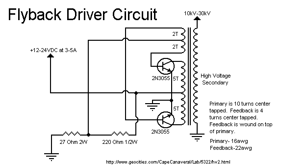
This is probably the most well known flyback transformer driver circuit. It uses two 2N3055 power transistors in a push-pull oscillator configuration. The value of the resistors is not that critical. In fact you can even use a 1/2W for the 27 ohm resistor, but it may burn out if it is left to run for a long time. This circuit will accept voltages up to about 24V, but I would not go any above this as you risk destroying the flyback transformer. Try to find an old flyback. It should have a rather disk shaped high voltage winding, rather than a cylindrical one. Also it should not have a rectifer built in. The rectifer decreases the performance of this circuit greatly since it cuts off the other cycle. You should not run this on any power supply which is expensive. This is because the circuit will produce lots of feedback and can destroy sensitive components in a decent linear or switching power supply. If you do run it on a good power supply be sure to put a large filter capacitor across the input of this circuit. A choke is also recommended. You may also get a shock off of components on the primary side, this just shows how much cemf is generated.

The primary is a handwound coil wound on the opposite side of the secondary consisting of ten turns of 16 guage solid wire. The feedback winding is wound on top of the primary winding with four turns of 22 guage solid wire. Both windings are center tapped. If there is no high voltage from the secondary winding then try reversing the leads that go to the bases on the transistor. These must be in phase for proper operation. The 2N3055s can be replaced with about any large horizontal output transistor, in fact this is actually better. You can also use a PNP transistor, just reverse the polarity of the input.
This circuit will work somewhat good, depending on the flyback used, for a Jacob's ladder. Don't expect a very hot (thick) arc though. The 15-40kV ignition coil device is much works much better for a Jacob's ladder, but this circuit is great for a plasma globe.