 NOT for GELL-TYPE batteries
Parts:
 R1 = 0.1 ohm       P1 = 2K
 R2 = 3.3 ohm       P2 = 1K
 R3 = 220 ohm       C1 = 100uF/40V (Electrolytic)
 R4 = 2K7           C2 = 100pF (0.1nF)
 R5 = 1K            U1 = LM350
 R6 = 1K5           U2 = LM334
 R7 = 4K7           U3 = LM301A
 R8 = 1K8           Q1 = 2N3906
 R9 = 4K7           D1 = 1N4002
R10 = 1K5         Led1 = Red, 5mm
R11 = 33 ohm      Led2 = Green, 5mm
R12 = 100 ohm       S1 = Switch, ON-ON
R13 = 1K8
R2 = 3.3 ohm P2 = 1K
R3 = 220 ohm C1 = 100uF/40V (Electrolytic)
R4 = 2K7 C2 = 100pF (0.1nF)
R5 = 1K U1 = LM350
R6 = 1K5 U2 = LM334
R7 = 4K7 U3 = LM301A
R8 = 1K8 Q1 = 2N3906
R9 = 4K7 D1 = 1N4002
R10 = 1K5 Led1 = Red, 5mm
R11 = 33 ohm Led2 = Green, 5mm
R12 = 100 ohm S1 = Switch, ON-ON
R13 = 1K8
Notes:
The circuit furnishes an initial charge voltage of 2.5 Volt-per-cell at 25°C to rapidly charge a Lead-Acid battery.
The charging current decreases as the battery charges, and when the current drops to about 180mA, the charging circuit reduces the output voltage to 2.35 Volt-per-cell, floating the battery in a fully charged state. This lower voltage prevents the battery from overcharging, which would shorten its life. The LM301A (U3) compares the voltage drop across R1 with an 18-mV reference set by R2. The comparator's output controls the voltage regulator, forcing it to produce the lower float voltage when the battey-charging current passing trhought R1 drops below 180mA. The 150mV difference between the charge and float voltages is set by the ratio of R10 and R12. The red and green Led's show this state of the circuit.
At points A and B you would see approximately 18mV depending on the types of components used. At point C there is a current flow of approximately 2.3 milli-amps, again, depending on your choice of components and ofcourse the input voltage at 'Vin' of the LM350 regulator.
Led1 is a red led, and for Led2 you can also use a yellow or red one. Make sure that C1 is at least twice the input voltage. C2 is a small ceramic type. Vin is at least 18-20volt max about 30V. Switch S1 is a toggle or slide (ON-ON) switch of your choice. The regular on-off type will not work.
This circuit is not recommended for GELL-TYPE batteries since it draws to much current.
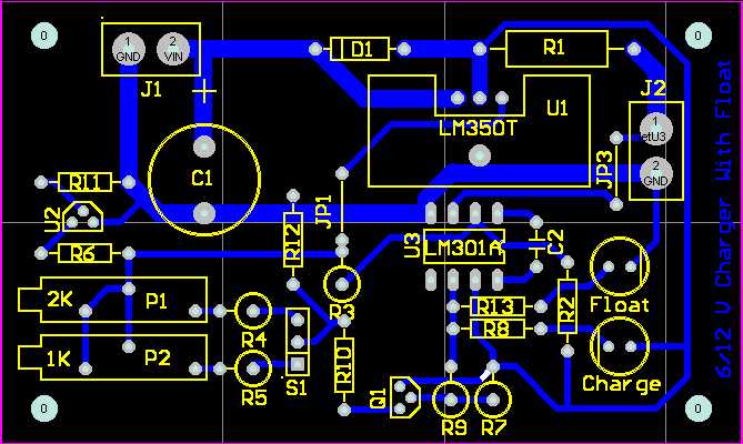
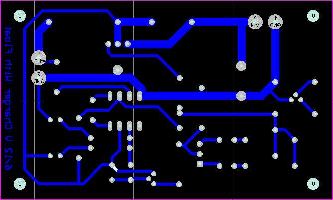
Below are the layout and pcb for this project, with thanks to Chaisaeng Euesakulkieat:
Back to Gadgets Menu page
Copyright © 1998 - Tony van Roon