An overview of switched mode power supplies or SMPS
Of necessity this is only a broad overview of switched mode power supplies or SMPS. The switched mode power supplies or SMPS owes its origins back to the days when valve or tube car radios needed the large HT supply, e.g. 150V DC to be generated from an automobile power system of nominally 12V DC.
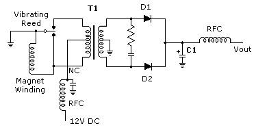
In those days the switched mode power supply took the form of a "vibrating reed" or vibrator which "chopped" up the 12V DC by electro-mechanical means and was then applied to a transformer, rectifier and filtering circuit to produce the much higher DC output.

Figure 1. - the vibrator type power supply
In principle only the electro-mechanical component has been replaced in favour of solid state electronics to produce a much more efficient, reliable and durable system.
Switched mode power supplies or SMPS as DC to DC Converters
Essentially switched mode power supplies or SMPS act as DC to DC converters. In these applications the switched mode power supply acting as a DC to DC converter first rectifes an AC input voltage (110V / 240V), converts it to DC and depending upon the design considerations chosen, chops this DC in a "chopper" and converts it to a higher or lower level of DC or perhaps both a higher AND lower level of DC. Typical modern applications include your computer power supply and the power supplies in your TV and Video sets.
Older televisions sets had power transformers which were bulky, heavy and quite expensive. Although modern solid state electronics have considerably reduced the power consumption of TV sets, the switched mode power supply has entirely replaced the power transformer leading to a substantial reduction in cost, size, weight and vastly improved efficiency in the use of power in a modern television set. Similar improvements and efficiencies brought about by switched mode power supplies can be seen in modern computers. As one example I serviced a video for my daughter - actually removed pieces of toast - it was a TEAC video and its power consumption was 240V 50 Hz 14 Watts!
Comparison of switched mode power supplies with other forms of power regulation
We have previously looked at:
Shunt regulated power supplies.
Linear regulated power supplies.
These type of regulators whilst relatively economical for low current requirements are notoriously inefficient, difficult to regulate with varying loads and suffer from residual power line ripple.
Switched mode power supplies or SMPS on the other hand while extending circuit complexity, offer significantly improved efficency (perhaps 80%), greatly reduced system weight and size and in higher current applications, reduced costs.

Figure 2. - comparison of a conventional transformer power supply efficency with a switched mode power supply
Switched mode power supplies or SMPS as DC to DC converters operate at 20 Khz or higher and utilize the energy stored during one portion of its operating cycle to supply power during the remaining segment of its operating cycle. It does however, suffer significantly in the ripple regulation it is able to maintain.
Linear regulators obtain improved regulation by virtue the series element is always conducting while the switched mode power supply is operating only during a portion of the overall operating period.
Attributes of switched mode power supplies, SMPS
As I said earlier the advantages of a SMPS are primarily lower weight, smaller size, higher efficiency, wide AC input voltage range and of course reduced costs for larger amounts of power being delivered. We will now consider these points individually.
low weight and smaller size come about because operation is at a signficantly higher frequency range and the inductive elements are vastly smaller and much cheaper.
higher efficiency occurs because the power transistor is swtched very rapidly between saturation (FULL ON) and cut off (FULL OFF) and there is very little power dissipation and it follows there are reduced heat sinking requirements.
wider AC input voltage range results from the flexbility in selecting the switching frequency and the transistor duty cycle which makes voltage adaption unnecessary.
reduced costs occur owing to the absence of large bulky power transformers, a huge reduction in volume and power dissipation, smaller material requirements and also smaller semiconductor devices.
Disadvantages of switched mode power supplies, SMPS
The largest disadvantage of switched mode power supplies is that they can not easily be employed by electronic hobbyists or even electronics technicians in a casual fashion owing to circuit complexity. A traditional 12V DC power supply providing 1A of current is well within the construction capabilities of every electronic hobbyist with some experience. A switched mode power supply on the other hand could prove a very daunting task.
An Overview Of SwitcheMode Power Supplies - Philips AN120 - 60 Kb
Looking at a switched mode power supply
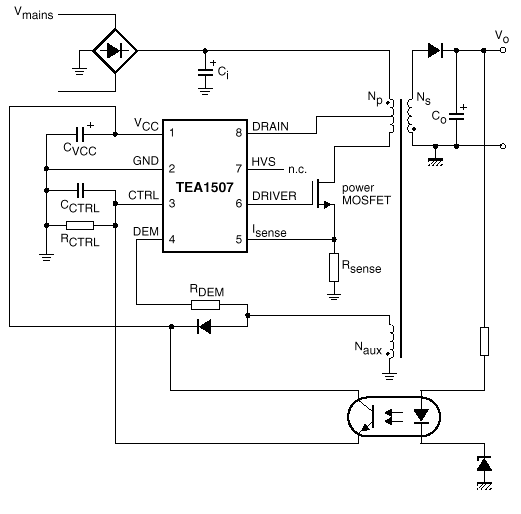
As the first example we will look at a SMPS based upon the Phillips TEA1507 which is described as "GreenChip® TMII SMPS control IC" and features Universal mains supply operation (70 to 276 V AC), the device can be used in all applications that demand an efficient and cost-effective solution up to 250 W.
The TEA1507 is the controller of a compact flyback converter, with the IC situated at the primary side. An auxiliary winding of the transformer provides demagnetization detection and powers the IC after start-up.
The TEA1507 operates in multimodes.

Figure 3. - a switched mode power supply using flyback configuration with secondary sensing
Download TEA1507 Data Sheet - 114 Kb
Looking at the newer STARplug ® TM switched mode power supply TEA152X series
These are new devices from Philips are designed for general purpose supplies up to 50 W.
The STARplug ® TM TEA152X series Application Note, AN00055 - 42 pages (989 Kb) provides us with a wealth of information.
There is also the TEA152X series Data Sheet - 20 pages - 114 Kb
The TEA152x family is the heart of a compact flyback converter, with the IC placed at the primary side. The auxiliary winding of the transformer can be used for indirect feedback to control the isolated output. This additional winding also powers the IC. A more accurate control of the output voltage and/or current can be implemented with an additional secondary sensing circuit and optocoupler feedback.
The TEA152x family uses voltage mode control. The frequency is determined by the maximum transformer demagnetizing time and the time of the oscillator. In the first case, the converter operates in the Self Oscillating Power Supply (SOPS) mode. In the latter case, it operates at a constant frequency, which can be adjusted with external components RRC and CRC . This mode is called Pulse Width Modulation (PWM). Furthermore, a primary stroke is started only in a valley of the secondary ringing. This valley switching principle minimizes capacitive switch-on losses.
Start-up and under voltage lock-out
Initially, the IC is self supplying from the rectified mains voltage. The IC starts switching as soon as the voltage on pin VCC passes the VCC(start) level. The supply is taken over by the auxiliary winding of the transformer as soon as
VCC is high enough and the supply from the line is stopped for high efficiency operation.
The STARplug ® TM TEA152X series Application Note, AN00055 is extremely comprehensive and provides step by step design procedures. Included in section 5 - page 37 - is the design of a 5V, 3 watt switched mode power supply including schematic, parts list and suggested PCB.
Conclusion on switched mode power supplies, SMPS
I said at the beginning this was a general overview however starting with "An Overview Of Switched Mode Power Supplies" - Philips AN120 (60 Kb) together with the other rich resources listed on this page you should be well on your way to a complete understanding of the topic.


