Infrared Remote Control Tester
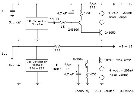
This is a fairly easy circuit that can be used to test TV and VCR remote controls. The infrared detector module (GP1U52X) (Radio Shack 276-137) produces a 5 volt TTL pulse train corresponding to the digital code of the particular remote control key pressed. In the lower circuit, the module output is normally low with no signal received and becomes a positive going pulse train when a signal is present. Other detector modules are available that have an inverted output as shown in the upper drawing which is the type I used, but I don't have the part number, I believe it was removed from a VCR. The pulse sequence represents the digital code of the particular key pressed along with possible manufacturer information. As the pulse train occurs, the 4.7uF capacitor is charged to about 3 volts and the capacitor voltage minus a diode drop appears across the 470 ohm resistor yielding a collector current from the 2N3904 or 2N3906 of about 5 milliamps. The collector current of the first stage flows into the base of the output transistor (MJE34 or 2N3053) which delivers around 250 mA into the indicator lamps. When the pulse train ends, the capacitor slowly discharges through the base of the first stage transistor allowing the Xmas tree lights to remain on for a about 1 second. The little Xmas lamps will operate over a wide voltage range, so you can use bulbs from almost any string, but bulbs from shorter strings (35 or less) will probably last longer operated at 5 volts.
The circuit can be powered from a small 9-12 volt DC, 250 mA or greater wall transformer. It may also need an additional 1000 uF filter capacitor across the DC output if the wall transformer does not have a built in capacitor. For use with a 9 volt battery, the incandescent lamps can be replaced with a regular LED and 680 ohm resistor and the output transistors can be replaced with small signal transistors (2N3904 or 2N3906). The total current drain will be about 25 mA with the LED lit, and 15 mA standby when the LED is off.

Transistor Schmitt Trigger Oscillator
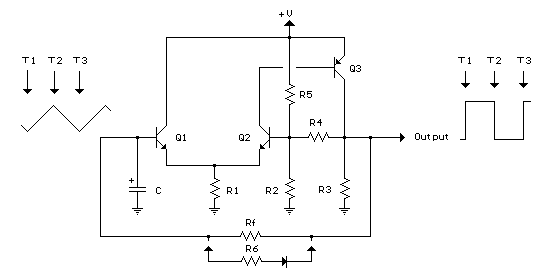
The Schmitt Trigger oscillator below employs 3 transistors, 6 resistors and a capacitor to generate a square waveform. Pulse waveforms can be generated with an additional diode and resistor (R6). Q1 and Q2 are connected with a common emitter resistor (R1) so that the conduction of one transistor causes the other to turn off. Q3 is controlled by Q2 and provides the squarewave output from the collector.
In operation, the timing capacitor charges and discharges through the feedback resistor (Rf) toward the output voltage. When the capacitor voltage rises above the base voltage at Q2, Q1 begins to conduct, causing Q2 and Q3 to turn off, and the output voltage to fall to 0. This in turn produces a lower voltage at the base of Q2 and causes the capacitor to begin discharging toward 0. When the capacitor voltages falls below the base voltage at Q2, Q1 will turn off causing Q2 and Q3 to turn on and the output to rise to near the supply voltage and the capacitor to begin charging and repeating the cycle. The switching levels are established by R2,R4 and R5. When the output is high, the voltage at the base of Q2 is determined by R4 in parallel with R5 and the combination in series with R2. When the output is low, the base voltage is set by R4 in parallel with R2 and the combination in series with R5. This assumes R3 is a small value compared to R2. The switching levels will be about 1/3 and 2/3 of the supply voltage if the three resistors are equal (R2,R4,R5).
There are many different combinations of resistor values that can be used. R3 should low enough to pull the output signal down as far as needed when the circuit is connected to a load. So if the load draws 1mA and the low voltage needed is 0.5 volts, R3 would be 0.5/.001 = 500 ohms (510 standard). When the output is high, Q3 will supply current to the load and also current through R3. If 10 mA is needed for the load and the supply voltage is 12, the transistor current will be 24 mA for R3 plus 10 mA to the load = 34 mA total. Assuming a minimum transistor gain of 20, the collector current for Q2 and base current for Q3 will be 34/20 = 1.7 mA. If the switching levels are 1/3 and 2/3 of the supply (12 volts) then the high level emitter voltage for Q1 and Q2 will be about 7 volts, so the emitter resistor (R1) will be 7/0.0017 = 3.9K standard. A lower value (1 or 2K) would also work and provide a little more base drive to Q3 than needed. The remaining resistors R2, R4, R5 can be about 10 times the value of R1, or something around 39K.
The combination of the capacitor and the feedback resistor (Rf) determines the frequency. If the switching levels are 1/3 and 2/3 of the supply, the half cycle time interval will be about 0.693*Rf*C which is similar to the 555 timer formula. The unit I assembled uses a 56K and 0.1 uF cap for a positive time interval of about 3.5 mS. An additional 22K resistor and diode were used in parallel with the 56K to reduce the negative time interval to about 1 mS.
In the diagram, T1 represents the time at which the capacitor voltage has fallen to the lower trigger potential (4 volts at the base of Q2) and caused Q1 to switch off and Q2 and Q3 to switch on. T2 represents the next event when the capacitor voltage has risen to 8 volts causing Q2 an Q3 to turn off and Q1 to conduct. T3 represents the same condition as T1 where the cycle begins to repeat. Now, if you look close on a scope, you will notice the duty cycle is not exactly 50% This is due to the small base current of Q1 which is supplied by the capacitor. As the capacitor charges, the E/B of Q1 is reverse biased and the base does not draw any current from the capacitor so the charge time is slightly longer than the discharge. This problem can be compensated for with an additional diode and resistor as shown (R6) with the diode turned around the other way.

Battery Equal Charge Indicator
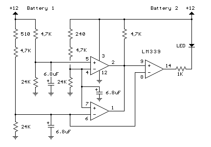
The circuit below illuminates an LED to indicate unequal charges between two 12 volt lead batteries. It can be used to verify that two batteries are connected in parallel or isolated since the LED will be off when the voltages are equal within a tollerance, or on if the voltage difference is greater than 100 millivolts. Three comparators and three voltage dividers are used to determine battery conditions. The upper left comparator (+) input at pin 5 is set to about 10 volts with battery #1 at 12 volts. The negative input (pin 4) is set to a slightly lower voltage by adding an additional 240 ohms to the voltage divider so that the output of the comparator will be positive when both battery voltages are equal and negative if battery 2 rises above battery 1 by 100 millivolts or more. The voltage at pin 5 is used as a reference for the lower comparator and the negative input of the lower comparator is set to a lower voltage with the addition of 510 ohms, so that the output will also be positive when the battery voltages are equal and negative when battery #1 is greater than #2 by 100 millivolts or more. The two comparator outputs are both connected to the positive input of the third comparator at pin 9 so that the LED will illuminate when either condition exists,
(Battery #1 > Battery #2) OR (Battery #2 > Battery #1).

Salt Water Battery
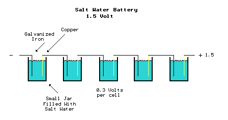
About 13 years ago, I made a salt water battery to operate a single AA battery quartz clock. It ran for several months until I got tired of adding water to compensate for evaporation. The batttery consisted of 5 cells each producing about 300 millivolts. As I remember, I used 5 small olive jars filled with about a cup of water and a tablespoon of salt to create 5 cells in series each producing about 300 millivolts for a total of around 1.5 volts. The positive electrode was made from a strip of double sided copper circuit board (about 1 inch by 4 inch) and the negative electrode was a similar sized strip of aluminum. I recently tried some galvanized iron instead of aluminum and found it produces a little higher voltage so the battery may be made with only 3 cells. But any two different metals used with salt water or citrus juice will create a low voltage battery. You might experiment using silver coins and copper pennies and various fruit juices to come up with a more powerful battery. The diagram below shows the 5 cells connected in series with the galvanized iron of one cell connected to the copper piece of the next. The battery produces a very low current of around 1 milliamp so it's not practical for much other than a quartz clock. You might get a low current LED to light using a few more cells and larger electrodes with greater surface area. You might also add a capacitor across the battery to supply higher current pulses for a flashing LED. It will probably operate the 1.5 volt flashing LED circuits shown on the main menu at a slow flash rate.
