THE ELECTRIC WAVE
ALKALINE
CHARGER
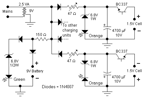 This circuit was specifically designed to recharge
alkaline cells. The unusual connection of the transistor in each charging unit
will cause it to oscillate, on and off, thus transferring the charge accumulated
in the capacitor to the cell. The orange LED will blink for around 5 times a second for a
1.37V cell. For a totally discharged cell the
blinking is faster but it will decrease until it will
come to a stop when the cell is charged. You may leave the cell in the charger
as it will trickle charge and keep it at around 1.6V. To set the correct voltage
you have to connect a fresh, unused cell and adjust the trimmer until
oscillations set in, then go back a little until no oscillation is present and
the circuit is ready to operate. You should use only the specified transistors,
LED colors, zener voltage and power rating because they will set the final
voltage across the cell. A simple 9V charging circuit was also included: it will
charge up to around 9.3V and then keep it on a trickle charge: the green LED
will be off while charging and will be fully on when the battery is close to its
final voltage.
This circuit was specifically designed to recharge
alkaline cells. The unusual connection of the transistor in each charging unit
will cause it to oscillate, on and off, thus transferring the charge accumulated
in the capacitor to the cell. The orange LED will blink for around 5 times a second for a
1.37V cell. For a totally discharged cell the
blinking is faster but it will decrease until it will
come to a stop when the cell is charged. You may leave the cell in the charger
as it will trickle charge and keep it at around 1.6V. To set the correct voltage
you have to connect a fresh, unused cell and adjust the trimmer until
oscillations set in, then go back a little until no oscillation is present and
the circuit is ready to operate. You should use only the specified transistors,
LED colors, zener voltage and power rating because they will set the final
voltage across the cell. A simple 9V charging circuit was also included: it will
charge up to around 9.3V and then keep it on a trickle charge: the green LED
will be off while charging and will be fully on when the battery is close to its
final voltage.
A 2.5VA transformer will easily charge up to 4 cells at
the same time although 2 only are shown in the schematic. In order
to minimize interference from one circuit to the other they have nothing in
common except the transformer and, in order to show a balanced load to the
transformer, half of the charging units will use the positive sinewave and the
other half the negative sinewave.
Make sure to use high beta transistors such as BC337-25 or better BC337-40.
Type BC337-16 might not work all the time.
All types of alkaline cells can be recharged: it will
take around 1 day for a discharged AA cell or 9V battery and up to several days
for a large D type cell. The best practice is not to discharge completely the
cell or battery but rather to give a short charge every so often although
admittedly this is not easy to achieve.
Do not attempt to recharge a totally discharged cell or a cell showing even the
slightest sign of damage.
5W
INVERTER
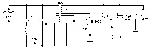 A single
transistor is all you need for this simple inverter. The main aim of this
circuit is to provide a suitable supply for all kind of low power battery
chargers that normally connect to the mains such as mobile phones, electric
shavers, etc, even an electronic neon light rated at 5W was successfully connected. Only easily obtainable components are used. The transformer is a
standard 10VA mains transformer with two 6V windings connected as shown in the
schematic. Frequency of operation is between 70 and 190Hz depending on the
nature of the load. This frequency is acceptable by most devices but obviously
it is not suitable to drive frequency dependent appliances such as clocks or
small motors that depend on the mains frequency in order to operate reliably.
The transistor will not require any additional heatsink if it is assembled on
the metallic case provided for the inverter. The neon glow light will give a
useful indication, and warning, on the presence of a dangerous voltage at the
output. A 2.5A fuse on the input supply line would be a useful addition.
Operation is simple: switch on the unit and connect the load keeping an eye on
the neon glow light which should be always on: certain switching chargers demand
an initial peak current effectively shorting the output and switching off the
neon: in this case you have to try repeatedly to connect the load until it
works. A temporary short at the output and a temporary voltage reversal at the
input will not damage the unit. Efficiency was not a design parameter however it
was measured to be between 50 and 60%. If you have a 110V mains
transformer and consequently a 110VAC output you should change the 0.1mF
capacitor to 0.22mF, 400V. The waveform is only
vaguely sinusoidal. Invert the connection of
one of the 6V windings if oscillations do not set in.
A single
transistor is all you need for this simple inverter. The main aim of this
circuit is to provide a suitable supply for all kind of low power battery
chargers that normally connect to the mains such as mobile phones, electric
shavers, etc, even an electronic neon light rated at 5W was successfully connected. Only easily obtainable components are used. The transformer is a
standard 10VA mains transformer with two 6V windings connected as shown in the
schematic. Frequency of operation is between 70 and 190Hz depending on the
nature of the load. This frequency is acceptable by most devices but obviously
it is not suitable to drive frequency dependent appliances such as clocks or
small motors that depend on the mains frequency in order to operate reliably.
The transistor will not require any additional heatsink if it is assembled on
the metallic case provided for the inverter. The neon glow light will give a
useful indication, and warning, on the presence of a dangerous voltage at the
output. A 2.5A fuse on the input supply line would be a useful addition.
Operation is simple: switch on the unit and connect the load keeping an eye on
the neon glow light which should be always on: certain switching chargers demand
an initial peak current effectively shorting the output and switching off the
neon: in this case you have to try repeatedly to connect the load until it
works. A temporary short at the output and a temporary voltage reversal at the
input will not damage the unit. Efficiency was not a design parameter however it
was measured to be between 50 and 60%. If you have a 110V mains
transformer and consequently a 110VAC output you should change the 0.1mF
capacitor to 0.22mF, 400V. The waveform is only
vaguely sinusoidal. Invert the connection of
one of the 6V windings if oscillations do not set in.
 Full astern to main
page
Full astern to main
page

Contact: 