THE ELECTRIC WAVE ![]()
POWER FLASHER
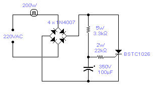 There is no need to resort to complex circuitry if what you
are looking for is a simple power flasher. The light will flash at around 1Hz with a 100W
bulb at a duty cycle of 50%. The max. load that can be driven with this circuit is 200W
and if you wish to have a different frequency you have to change the value of the
capacitor. Operation at 110VAC has not been tested although I expect it to work provided
the 5W resistor is set at about half the stated value. The SCR is manufactured by Siemens
but any other equivalent semiconductor should work fine. WARNING! - This circuit is
directly connected to the mains and proper safety precautions should be taken.
There is no need to resort to complex circuitry if what you
are looking for is a simple power flasher. The light will flash at around 1Hz with a 100W
bulb at a duty cycle of 50%. The max. load that can be driven with this circuit is 200W
and if you wish to have a different frequency you have to change the value of the
capacitor. Operation at 110VAC has not been tested although I expect it to work provided
the 5W resistor is set at about half the stated value. The SCR is manufactured by Siemens
but any other equivalent semiconductor should work fine. WARNING! - This circuit is
directly connected to the mains and proper safety precautions should be taken.
SCR OSCILLATOR
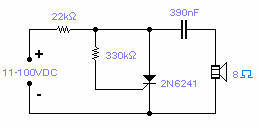 Silicon controlled rectifiers (SCR) can easily oscillate if
there is an inductor (a speaker coil in this case) which gives just enough extra voltage
to completely switch off the sustain current. In this way a new cycle may start and
oscillations set in. It operates over a wide range of supply voltage and components values
are not critical at all. Operational frequency in this circuit goes from 100Hz at 11V to
10KHz at 100V.
Silicon controlled rectifiers (SCR) can easily oscillate if
there is an inductor (a speaker coil in this case) which gives just enough extra voltage
to completely switch off the sustain current. In this way a new cycle may start and
oscillations set in. It operates over a wide range of supply voltage and components values
are not critical at all. Operational frequency in this circuit goes from 100Hz at 11V to
10KHz at 100V.
ZENER OSCILLATORS
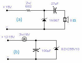 These two circuits are interesting from an academic point of view. Their practical
implementation is rather critical and it is not easy to get steady operation. Circuit (a)
requires a "cooked" zener: connect it first to a constant current generator,
then increase the current until the voltage across the zener starts to decrease. Reduce
the supply current and wait a few minutes until it really warms up. The zener is now ready
for the circuit: increase the voltage slowly until it oscillates (1KHz in the circuit
shown). You may need to decrease the voltage once oscillation takes place. With suitable
circuit components it will oscillate up to 20MHz. Circuit (b) will oscillate at a very low
frequency, normally 2-5Hz, provided the voltage is increased very slowly, loading is
critical and you may find that a slightly different lamp will work better. Higher voltage
zeners work better than low voltage zeners and the circuits operate only with the
specified types. The reasons for the oscillations are unknown, although, for circuit (b)
it is felt that some kind of reversible thermal breakdown is at work.
These two circuits are interesting from an academic point of view. Their practical
implementation is rather critical and it is not easy to get steady operation. Circuit (a)
requires a "cooked" zener: connect it first to a constant current generator,
then increase the current until the voltage across the zener starts to decrease. Reduce
the supply current and wait a few minutes until it really warms up. The zener is now ready
for the circuit: increase the voltage slowly until it oscillates (1KHz in the circuit
shown). You may need to decrease the voltage once oscillation takes place. With suitable
circuit components it will oscillate up to 20MHz. Circuit (b) will oscillate at a very low
frequency, normally 2-5Hz, provided the voltage is increased very slowly, loading is
critical and you may find that a slightly different lamp will work better. Higher voltage
zeners work better than low voltage zeners and the circuits operate only with the
specified types. The reasons for the oscillations are unknown, although, for circuit (b)
it is felt that some kind of reversible thermal breakdown is at work.
220V MAINS MONITOR
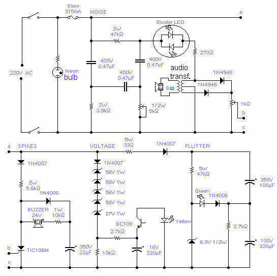 With this circuit you will be able to monitor the quality of the mains. There are
4 distinct sections, each supervising a parameter pertinent to the quality of the supply
line. The noise section consists of a 50Hz filter and a speaker where you will hear the
noise present on the line. The bicolor LED should be adjusted for the least light with the
5k pot and gives a visual indication of noise or asymmetry in the wave. The second section
will detect any spike which is overimposed on the mains voltage: adjust the pot so that it
will not trip if you just switch on the light, sensitivity is high enough to detect a
switching operation from a close neighbor. The buzzer will beep for about 1sec anytime
there is a spike. The actual voltage is detected with section 3: the yellow led will blink
at a rate of 6 Hz but will visibly double to 12 Hz for a 10% increase or will come to a
halt for a 10% decrease of the voltage. The last section will show the flutter or slow
variations of the mains voltage. The circuit will work for a 220V mains: for 230V
operation, change the 27V zener to 39V and for 60Hz operation change the 3.9k resistor to
3.3k and the 47k resistor to 39k. Operation at 110V will call for a major redesign of the
component values and has not been attempted.
With this circuit you will be able to monitor the quality of the mains. There are
4 distinct sections, each supervising a parameter pertinent to the quality of the supply
line. The noise section consists of a 50Hz filter and a speaker where you will hear the
noise present on the line. The bicolor LED should be adjusted for the least light with the
5k pot and gives a visual indication of noise or asymmetry in the wave. The second section
will detect any spike which is overimposed on the mains voltage: adjust the pot so that it
will not trip if you just switch on the light, sensitivity is high enough to detect a
switching operation from a close neighbor. The buzzer will beep for about 1sec anytime
there is a spike. The actual voltage is detected with section 3: the yellow led will blink
at a rate of 6 Hz but will visibly double to 12 Hz for a 10% increase or will come to a
halt for a 10% decrease of the voltage. The last section will show the flutter or slow
variations of the mains voltage. The circuit will work for a 220V mains: for 230V
operation, change the 27V zener to 39V and for 60Hz operation change the 3.9k resistor to
3.3k and the 47k resistor to 39k. Operation at 110V will call for a major redesign of the
component values and has not been attempted.
ULTRA LOW FREQUENCY RECEIVER
 The
frequency covered is from 0.1Hz to 10Hz and useful signals are received up to 16Hz. The
first Op-Amp, properly shielded, must be installed close to the antenna (1-3m long) and
connected to the rest of the circuit with a 5-core shielded cable. Adjust the 100k trimmer
so that the DC setting at the output of the OPA124 does not change when turning the 220k
sensitivity pot. A low pass filter followed by a notch filter take care of the mains
induced noise. The values in brackets are good for a 60Hz mains. 1% components should be
used for the 3 resistors and 3 capacitors of the notch filter. A voltage controlled
oscillator gives an audible frequency that follows the input signal and it is very handy
if the unit is made portable although I found that just walking around is enough to bury
the signal being received. The output signal goes first to a meter and then is available
for the connection to a data logger, which is an almost essential part of the receiver.
Sensitivity is quite adequate: any TV set switching on the area will be detected. There
are also a host of other mysterious signals of unknown origin. The input protection diodes
are special low leakage type and should not be replaced by standard diodes.
These diodes can be dispensed with if the antenna is installed with care and
away from strong electric fields. The diodes
connected to the meter are Schottky diodes and will provide a bias against very small
signals (mostly noise) which will not go through to the data logger. Pin connection for
OPA124: 1 and 5: DC set, 2 and 3: inverting and non-inverting, 6: output, 8: substrate.
Pin connection for LF412: 2 and 3: inverting and non-inverting, 1: output, 6 and 5:
inverting and non-inverting, 7: output.
The
frequency covered is from 0.1Hz to 10Hz and useful signals are received up to 16Hz. The
first Op-Amp, properly shielded, must be installed close to the antenna (1-3m long) and
connected to the rest of the circuit with a 5-core shielded cable. Adjust the 100k trimmer
so that the DC setting at the output of the OPA124 does not change when turning the 220k
sensitivity pot. A low pass filter followed by a notch filter take care of the mains
induced noise. The values in brackets are good for a 60Hz mains. 1% components should be
used for the 3 resistors and 3 capacitors of the notch filter. A voltage controlled
oscillator gives an audible frequency that follows the input signal and it is very handy
if the unit is made portable although I found that just walking around is enough to bury
the signal being received. The output signal goes first to a meter and then is available
for the connection to a data logger, which is an almost essential part of the receiver.
Sensitivity is quite adequate: any TV set switching on the area will be detected. There
are also a host of other mysterious signals of unknown origin. The input protection diodes
are special low leakage type and should not be replaced by standard diodes.
These diodes can be dispensed with if the antenna is installed with care and
away from strong electric fields. The diodes
connected to the meter are Schottky diodes and will provide a bias against very small
signals (mostly noise) which will not go through to the data logger. Pin connection for
OPA124: 1 and 5: DC set, 2 and 3: inverting and non-inverting, 6: output, 8: substrate.
Pin connection for LF412: 2 and 3: inverting and non-inverting, 1: output, 6 and 5:
inverting and non-inverting, 7: output.
ELECTRIC FIELD DETECTOR
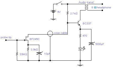 The circuit will come handy when you have to follow the
mains wires buried in the wall or even water pipes provided they are not too far away
(2-4cm max). It will also detect a conversation on a telephone cable without actually
touching it (for testing purposes only) and it works as a microphone if you keep a plastic
kitchen foil between the probe tip and your mouth. The probe is just the 12mm long gate
lead of the transistor. The 33M resistor should be cut short and soldered where the lead
enters the transistor case. Connection to the other part of the circuit is via a standard
coaxial cable of any length. The input is not protected and a pair of low leakage diodes
(JPAD5) could be connected back to back between gate and ground. I did not find them
necessary: I covered, with a small piece of plastic sponge, the probe tip to avoid direct
contact with electrified surfaces and used a minimum of care when handling the probe.
The circuit will come handy when you have to follow the
mains wires buried in the wall or even water pipes provided they are not too far away
(2-4cm max). It will also detect a conversation on a telephone cable without actually
touching it (for testing purposes only) and it works as a microphone if you keep a plastic
kitchen foil between the probe tip and your mouth. The probe is just the 12mm long gate
lead of the transistor. The 33M resistor should be cut short and soldered where the lead
enters the transistor case. Connection to the other part of the circuit is via a standard
coaxial cable of any length. The input is not protected and a pair of low leakage diodes
(JPAD5) could be connected back to back between gate and ground. I did not find them
necessary: I covered, with a small piece of plastic sponge, the probe tip to avoid direct
contact with electrified surfaces and used a minimum of care when handling the probe.
SCR INVERTER
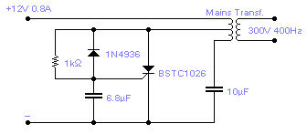 The
only drawback with this circuit is that it might latch in the conducting state if the load
is too heavy or if there is a short at the output, this requires some kind of protection,
on the input line, in the form of a fuse or similar. The transformer used is a 10W mains
type with 6V+6V windings on the SCR side and a 110V+110V windings, in series, at the
output. Efficiency is 50% and the ideal load is equivalent to a 22k resistor, 5W. The
output waveform is vaguely sinusoidal at a frequency of 400Hz.
The
only drawback with this circuit is that it might latch in the conducting state if the load
is too heavy or if there is a short at the output, this requires some kind of protection,
on the input line, in the form of a fuse or similar. The transformer used is a 10W mains
type with 6V+6V windings on the SCR side and a 110V+110V windings, in series, at the
output. Efficiency is 50% and the ideal load is equivalent to a 22k resistor, 5W. The
output waveform is vaguely sinusoidal at a frequency of 400Hz.
SOUND TRIGGERED FLASH
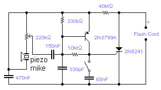 If
you wish to take a picture of a fleeting event which generates a sound, you can do it with
this sound activated trigger. It does not require any power supply: it feeds on the high
voltage available on the flash trigger terminal. Any economic ceramic microphone is
suitable for the purpose. The 68nF capacitor introduces a small delay in the operation of
the flash and may help in getting the picture in exactly the right moment although you
should expect to take several shots for best results. With this circuit you will be able
to catch a cork leaving the champagne bottle or the moment a balloon is punctured. The
whole circuit could be assembled in the mike housing making a very compact device.
If
you wish to take a picture of a fleeting event which generates a sound, you can do it with
this sound activated trigger. It does not require any power supply: it feeds on the high
voltage available on the flash trigger terminal. Any economic ceramic microphone is
suitable for the purpose. The 68nF capacitor introduces a small delay in the operation of
the flash and may help in getting the picture in exactly the right moment although you
should expect to take several shots for best results. With this circuit you will be able
to catch a cork leaving the champagne bottle or the moment a balloon is punctured. The
whole circuit could be assembled in the mike housing making a very compact device.
![]() Eager for more
Eager for more
 Full
astern to main page
Full
astern to main page
![]()
