
|
The Audio Pages |
| Elliott Sound Products | Effects Of Source Impedance on Loudspeakers |
Copyright ![]() 2001 - Rod Elliott (ESP)
2001 - Rod Elliott (ESP)
Page Created 22 Jul 2001
This is not the final word on this topic, and I am sure that others with more (and better) equipment than I have could do much more. An hour or so of testing is hardly a fully scientific study, but the results agree with expectations for voltage and current drive - what came as a surprise was just how nasty negative impedance really is.
This article was prompted by a reader who did some simulations of a loudspeaker having no voice coil resistance. Of course, this is not possible, but driving with negative impedance can theoretically accomplish the same thing.
Negative impedance has been around for quite some time (probably about 50 years, maybe more), but I suspect that I have one of the few amplifiers around that can be preset to any impedance between -16 Ohms and +32 ohms. To this end, it was reasonably easy to test, and I used 42Hz as the test frequency - being representative of a typical bass signal (open "E" on a bass guitar). Just to make matters as bad as they could be, this is also very close to the resonant frequency of the test loudspeaker and enclosure.
I used a sound level meter at close range (100mm) connected to my oscilloscope to see the actual loudspeaker waveform. The speaker is a 4 Ohm 300mm Cerwin Vega subwoofer, in a 28 litre sealed box. This box has been used many times as a test system for the Electronically Assisted Subwoofer (see EAS project), described on these pages.
During these tests I made no real attempt to use zero crossing switching, since this was difficult for a quick test (my tone burst generator is on the blink and needs repair - one day). The lower trace is the output from the signal generator, and switching could - and did - take place whenever I switched the output.
The upper trace of each oscilloscope screen photo is the signal taken directly from my sound level meter, and the lower trace is the input signal. I made no real attempt to maintain any specific level, since it was immediately apparent that this made little difference.
The waveforms displayed are exactly as measured, and the phase and timings were not tampered with in any way. The input signal was not bandwidth limited, nor was the amplifier output - the test results are therefore "worst case".
Transients are generated at the moment of switching - it is predominantly these that are of interest - a photo of an oscilloscope trace of a 42Hz waveform is fundamentally boring, whatever the source. The oscilloscope traces shown were captured with my digital camera - less than ideal, but it works (other than the ghostly image of the camera reflected in the front of the display).
Voltage drive is the most common way to drive loudspeakers. In theory, a "perfect" voltage amplifier has zero ohms output impedance, but this is never achieved in practice. Output impedances of 0.1 ohm or less are not uncommon at low frequencies, representing a "damping factor" of 80 or more.
 ...
...
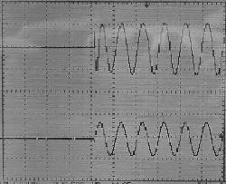
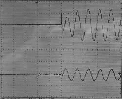
Voltage Drive - Z = <0.5
Ohms
One might say that this is text book performance. There is evidence of the switching transient, but overall this combination is well behaved. This is the most common connection for loudspeakers, and seems to be about as good as it gets. Overhang (ringing after the signal has gone) is almost non-existent.
With a pure current drive signal, the input determines the current that flows through a loudspeaker (or other) load. This is rarely used in practice, as it is unsuitable for driving speakers. Using a defined impedance means that the amplifier's output is dependent on the load impedance at any given frequency, but in a way that is predictable. This can be used to advantage, but is most commonly (and IMHO incorrectly) frowned upon. Generally, I would suggest that the amplifier's output impedance should be no greater than the speaker impedance (and preferably less).
 ...
...
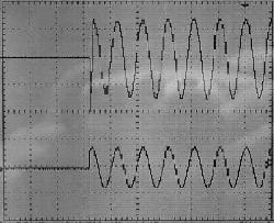
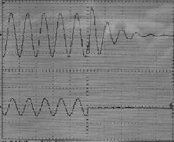
Current Drive - Z = +3
Ohms
The switching transient is still in evidence, as is to be expected - the big spike is a result of the switching point, and is not unique to current drive. The attack is almost perfect, but a slight ringing is apparent when signal is removed. Although this is quite visible, it is inaudible (at least in my workshop), and since bass signals don't normally stop partway through a cycle, it is unlikely to be audible in a typical room, whose response will be far worse than the speaker.
This is the same as the previous definition, but in this example, the output impedance was increased to 32 ohms - this is 8 times the quoted impedance of the speaker I used.
 ...
...
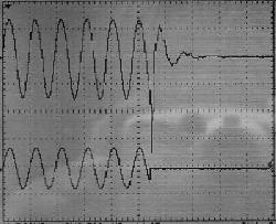
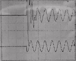
Current Drive - Z = +32
Ohms
This is an extreme impedance, and would never be used in practice. There is a slow attack, with the signal building up to the steady state level. Considerable ringing is apparent when the signal is removed. This is both visible and (in my workshop, only just) audible. This is not a good combination for hi-fi, but may be quite acceptable for a bass guitar amp (for example), as the colouration simply adds timbre to the sound of the instrument. The switching transient is almost non-existent, as the energy is converted into underdamped cone movement instead.
This is "slow" bass, with a wooliness that may be attributed to some valve amplifiers - especially those with no (or very little) feedback. There are many people who like the sound like this, and this is perfectly OK. Each to his own, and all that. In general, the impedance is too high in my opinion.
Negative impedance does exactly what it implies - when the load is increased (with a lower impedance), the signal applied to the load increases (i.e. the exact opposite of what normally happens). This results in an intrinsically unstable system, and great care must be taken to prevent the creation of an oscillator.
 ...
...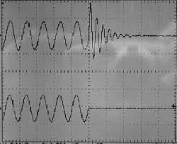
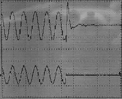
Current Drive - Z = -3
Ohms
The performance of this combination is completely unacceptable in every sense of the term. This combination could never be used in practice, for any reason. There is a vicious attack, with the signal doing something at a frequency completely unrelated to the input signal - unrelated in any way that I can determine, at least. Considerable ringing is apparent (again at an unrelated frequency) when the signal is removed. This is highly visible and audible, and the sound of the attack and decay is grossly inferior to any other combination. The others (using positive impedance) have some character, but it is related to the signal, and makes some sort of musical sense.
To add insult to injury, the amp decided to become an oscillator (at about 15Hz) on a few occasions, this being one of the risks of negative impedance. It subsided, but was a little disconcerting. I doubt that this is high on the "desirable" list for most audiophiles.
Reducing the negative impedance to -1.5 Ohms stopped the oscillation entirely, but the effect on the attack and decay performance was merely a minor reduction of the many artefacts created, and was still quite unacceptable.
As I mentioned in one or more articles on these pages, I have never found a cone speaker that "likes" negative impedance. Horn compression drivers seem quite happy and this is a test that I may now be forced to perform to find out what it does, and how it affects the sound (other than an apparent improvement in bandwidth).
The net result of these tests indicate what has long been known - that voltage drive remains the best choice for most loudspeakers, regardless of some desirable characteristics of defined current drive. With additional internal damping, moderate current drive can modify the Qts of the loudspeaker driver, and allow an enclosure design that is (typically) larger than optimal for flattest amplitude (Butterworth) response.
There was recently an article in Electronics World, where it was claimed that current drive helps to compensate for the resonant peak and voice coil inductance in a driver. While this is undoubtedly true (I've been doing it for many, many years), the designer must be very careful to ensure that the enclosure is particularly well damped, to avoid "overhang" when the signal is removed. This will typically manifest itself as poorly defined bass, particularly on transients, since the speaker must rely primarily on its own devices for damping.
Overall, this exercise has simply proven that which has already been proven by so many before me ...
| Copyright
Notice. This article, including but not limited to all text and diagrams,
is the intellectual property of Rod Elliott, and is Copyright |