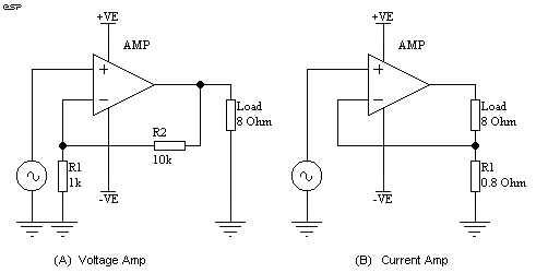
Figure 1 - Voltage and
Current Amplifiers

| Elliott Sound Products | Project 56 |
Is this a project or an article? Since you may have arrived here from either index, you might be a little confused. This is fine, as it has elements of both, but lacks the in-depth analysis of other articles, and also lacks the application of a final design that is common to my projects. This is for the experimenter. No further work will be done to refine formulae or produce "magic" spreadsheets to allow you to determine the impedance that is best for a speaker / enclosure combination or anything else. Readers' contributions are of course welcome, and I would be interested to hear about any massive improvements that were made to systems using these techniques. (Or minor improvements, for that matter.)
The idea of being able to vary the output impedance of a power amplifier has been around for a long time. I have used these techniques for over 30 years in various designs, and much as I would like to be able to claim otherwise, I was by no means the first.
The technique has been used to drive spring reverb units, and various other transducers where current drive is preferable to voltage drive. The latter is what we all strive for with power amplifiers - a perfect (ideal) voltage amplifier has zero ohms output impedance, and the amplitude does not change as the load varies. Loudspeakers are very non-linear loads, and the impedance will change at different frequencies for all sorts of reasons.
So voltage drive maintains a constant voltage across the load, while a current drive circuit will produce exactly the same current into the load - in both cases regardless of impedance. In reality neither approach is ideal ...
Not so much a real project as a field day for experimenters, this article describes the methods you can use to tailor an amplifier to a specific driver. Much is empirical (i.e. design by experiment, trial and error), and although formulae are possible, the load presented by a typical loudspeaker is very complex and leaves big holes in the final result if the maths are allowed to take over. Having said that, good results can be obtained by either method (theoretical or practical), so here goes ...
Figure 1 shows two amplifiers (shown as opamps), with (a) being conventional voltage drive, and (b) is current drive. The output impedances are in the order of zero ohms and infinite ohms in each case (this IS a theoretical discussion at the moment!). The gain will appear to be exactly the same for each into an 8 ohm resistive load, but will change based on load for the current amp. We shall see that this is not really the case - some power is lost in the series feedback resistor. The voltage amp has the same gain regardless of load.

Figure 1 - Voltage and
Current Amplifiers
The feedback is applied differently to achieve the desired result, as can be seen, although the difference is not at all subtle at first glance, as you look more closely you will see that it really is a simple rearrangement of feedback resistances. With the 8 ohm load, both amps have a gain of 11, but the series feedback in (B) actually means that the gain to the load is 10. With 1V AC signal applied, the voltage amp will develop 15.125W (11V at 8 ohms) into the load. The current amp will develop 12.5W (10V at 8 ohms) into the load, with 0.125W dissipated as heat in R1. This will remain constant for all load impedances.
Where things get interesting is when the load impedance changes. Should the load increase to 16 ohms (such as at resonance), the voltage amp will produce the same voltage, so power is halved. The current amp will provide the same current, so power into the load is increased fourfold to 50W, with the same 0.125W lost in the series feedback resistor. This of course assumes that the power supply voltage is high enough to allow the amp to do this without clipping.
Likewise, with a dip in impedance to 4 ohms, the voltage amp will provide double the power (30.25W - again assuming the the supply can now provide the necessary current), but the current amp will only produce 6.25W under the same conditions.
Which of these approaches is correct? For resistive loads it does not matter - both will perform identically except for the slightly lower gain of the current amp (this is easily compensated for). With loudspeaker loads, neither is ideal. Power to the load will vary widely depending on the impedance, which in turn depends upon frequency. The voltage amp will create a dip in response at each frequency where the impedance rises (and a rise wherever there is a lower impedance), and the current amp will do exactly the opposite.
By applying a mixture of both forms of feedback, it is possible to define the output impedance at any value between the two extremes. To emulate a valve amp for example, an output impedance of about 4 to 6 ohms is needed, assuming an 8 ohm load (this is the assumed nominal load impedance for all examples cited).
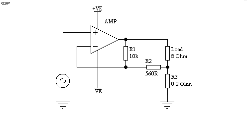
Figure 2 shows the arrangement used, and with the values shown the output impedance is a bit under 4 ohms. We could simply use a 4 ohm resistor in the amp's output, but this will waste much of the amplifier power, which will be dissipated in the resistor instead of the load. The same power output is available from a current amp as a voltage amp (give or take a fraction of a dB to account for the series feedback resistor).

Figure 2 - A Four Ohm
Output Impedance Amplifier
As can be seen, there is minimal additional complexity to achieve this result, and in my experience the final exact impedance is not overly critical, given the "real world" variations of a typical loudspeaker.
The no-load voltage is 18.8V with an input of 1V, and this drops to 12.8 at 8 ohms, and 9.7V with a 4 ohm load. These voltages are measured across the load, ignoring the voltage drop of the series feedback resistor.
From this, we can calculate the exact output impedance from
Il = Vl / Rl (where Il=load current, Vl=load Voltage and Rl=Load resistance)So we have created an amp with an output impedance of 3.75 ohms, with very little loss (just over 0.5W is lost in the 0.2 ohms series feedback resistor with 20W output into 8 ohms). To see if this is useful, we will now have a look at what happens when the load impedance doubles or halves.
Zo = (Vu - Vl) / Il (where Zo=output impedance, Vu=unloaded voltage, Vl=loaded voltage)Il = 12.8 / 8 = 1.6
Zo = (18.8 - 12.8) / 1.6 = 6 / 1.6 = 3.75 ohms
With a 16 ohm load, the power into the load falls to 14.6W, or about 1.37 dB. Contrast this with the conventional low impedance amp whose power will fall by 3dB (i.e. half).
When the impedance is reduced to 4 ohms, the output power is now 23.5W (an increase of 0.7dB), while a conventional amp would be producing 40W - an increase of 3dB.
Somewhere, there is a magical impedance that will give almost the same power into any load from double to half the nominal, give or take a dB or so. I am not about to test all possibilities, but having experimented with the concept for many years I am quite convinced that there are practical benefits to the use of modified current drive, where the impedance is defined. The exact impedance will depend to a very large degree on just what you are trying to achieve.
It has been suggested that loudspeaker intermodulation distortion is dramatically reduced by using a high impedance source (but by whom I cannot recall - I do know that one site I looked at was Russian, and a reader sent me a translation many months ago). I have experimented with this idea to some extent, but have been unable to prove that this is the case - at least with the drivers I tried it with.
This does not mean that the claim is false, but I am unable to think of any valid reason that could account for such driver behaviour. It is interesting anyway, and some of you might like to carry out a few experiments of your own. I would be most interested to hear about your results should you decide to test this theory - preferably more thoroughly than I did.
By adjusting the impedance of an amplifier, the total Q (Qts) of a loudspeaker can also be altered, so driver behaviour in a given sized box can be changed. This can be used to adapt an otherwise unsuitable loudspeaker to a speaker enclosure, but does have limitations in terms of the overall variation that can be achieved.
More variation can be achieved by virtue of the fact that it is now possible to either retain or increase the power delivered to a loudspeaker at resonance, so that the ultimate -3dB frequency may be lowered from that theoretically claimed for a loudspeaker / enclosure combination. Care is needed, since too much additional power will make the speaker boomy, and usually additional internal damping is needed to compensate for the minimal damping factor provided by the amplifier. With the amplifier output impedance set at 4 ohms, damping factor into an 8 ohm load is 2 - a far cry from the figures of several hundred typically quoted. These (of course) fail to take into consideration the resistance of the speaker leads, and loudspeakers themselves are usually compromised by the crossover network, so the damping factor is not always as useful as it might seem.
The results of using modified impedance can be very satisfying, allowing a useful extension of the bottom end. My own speakers are driven from a 2 ohm amplifier impedance, and there is no boominess or other unpleasantness, but a worthwhile improvement in bass response is quite noticeable.
Again, this has been about for many years, but I have only found one driver type that seems to obtain any improvement from its use - horn loaded compression drivers. All cone speakers (including horn loaded) sound worse with negative impedance, but you might have some weird driver that can benefit from a negative impedance amp.
As the name suggests, when a negative impedance amp is loaded, the output voltage rises. The greater the load, the more output is applied. This is very risky, and negative impedance amplifiers can easily oscillate when connected to a reactive load such as a loudspeaker. Indeed, negative impedance oscillators have been with us for many years in RF (and other) work, and there are quite a few electronic components that exhibit negative impedance. So, not new, but interesting.
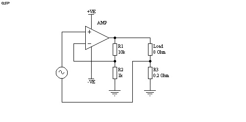
Figure 3 shows how the circuit is rearranged to accomplish this most bizarre of ideas. By simply substituting the "real" earth connection for the junction of load and series feedback resistor, the voltage developed across the resistor now increases the gain by adding to the input signal voltage.

Figure 3 - A Negative
Impedance Amplifier
This circuit with the values as shown will provide an open circuit load with 11V (as with a conventional mplifier as shown above), but when the load is applied the voltage increases as the load resistance is reduced. With the values shown, the load voltage will increase from 11V to 14.7V with an 8 ohm load, rising to 22V with a 4 ohm load. A quick calculation using the formulae above will show that the output impedance is about -2 ohms with an 8 ohm load, rising (falling?) to -4 ohms with a 4 ohm load.
The negative impedance amp is by its very nature unstable - the output impedance will continue to fall (become more negative) as the load is reduced, until at some point positive feedback exceeds negative feedback and the circuit will oscillate. Another undesirable side-effect is that distortion is increased, because negative feedback (which reduces distortion) is being counteracted by positive feedback. Again, this is a non-linear function, and the results are unpredictable at best. Reactive loudspeaker loads can cause a negative impedance amp to oscillate, either at the frequency between the loudspeaker's resonance and box resonance (where impedance falls), or at some other frequency determined by crossover components. Such oscillation can damage speakers (and ears!), so care is needed to ensure that this cannot happen. Low values of negative impedance (not less than -4 ohms) are strongly recommended.
I have found that only relatively small amounts of negative impedance are useful in practice. For example, one could use negative impedance to remove the resistance of the speaker cable and crossover components, although the results will not be as good as expected, and probably far worse. Even with a negative impedance of about 1 ohm, most speakers will show signs of "displeasure", and amplifier distortion will be increased - usually by an amount that is disproportional to the feedback factor.
This "project" is not really a project at all (which is why it has also been included in the articles index), but more of a starting point for experimenters. The circuits shown will all work with "real" amplifiers, but great care and considerable testing are needed to ensure that the results you actually obtain are providing a real benefit.
It is too easy to make a change such as shown here, and fully believe that the result is an improvement, where in reality (as eventually discovered after extensive listening and comparison) the opposite is true. While negative impedance may be found useful for horn compression drivers, it is unlikely (in my experience) to provide any benefit at all to cone loudspeakers.
Positive impedance can produce an improvement in bass response, but the cost can be high - boomy, over-accentuated bass at resonance, usually accompanied by a loss of bass "speed" and definition. There will be more freedom for the speaker cone to waffle about after the signal has gone ("overhang"), and it is rare that a speaker driven by a higher than normal impedance will perform well without additional damping in the enclosure.
There is no doubt that at output impedances in the order of 4 to 6 ohms your amp will sound more like a valve amp (but without the distortion), but it is up to you to decide if this is what you really want to do. The technique works well for guitar amps, as it allows the speaker to add its own colouration to the sound, which adds to the overall combination of distortion and other effects to produce pleasing results. For Hi-Fi the case is less clear, and experimentation is the only way you will ever find out for sure.
| Copyright Notice. This article, including but not limited to all text and diagrams, is the intellectual property of Rod Elliott, and is Copyright (c) 2000. Reproduction or re-publication by any means whatsoever, whether electronic, mechanical or electro- mechanical, is strictly prohibited under International Copyright laws. The author (Rod Elliott) grants the reader the right to use this information for personal use only, and further allows that one (1) copy may be made for reference while constructing the project. Commercial use is prohibited without express written authorisation from Rod Elliott. |