 |
 |
 |
 |
 |
 |
 |
 |
 |
 |
 |
 |
 |
 |
 |
 |
 |
 |
 |
 |
 |
 |
 |
 |
 |
 |
 |
 |
 |
 |
|
|

|
|
|
Return to John K's...DIY Speaker page |
|
|
|
|
<Back |
|
|
|
|
|
A Novel Way to Measure the Acoustic Output of Individual Drivers of a Loudspeaker |
|
|
|
After presenting my method for measuring the individual driver acoustic output for speakers using a series crossover I thought to myself, there must be an easier way to do this. It didn't take long to arrive at a simpler method that involved measuring only the speaker's acoustic response, with all the drivers connected, amd then doing a little data manipulation. The data manipulation, which can be don internal to the IMP or LAUD, involves simple summing of several response curves. If your measurement software doesn't has the capability to sum response data files, the summing can usually be done using design software, such as Soundeasy or LspCAD. An othe alternative is using the Frequency Response Combiner (FRC) at the Frequency Response Consortium (FRC) page. The procedure can be used for any speaker and is not limited to those using series crossovers. |
|
|
|
 |
|
|
|
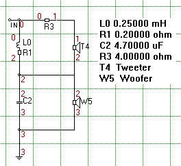
As an example of the procedure I will use a speaker with a series crossover since this is where the procedure is particularly useful. This is the same speaker used as the example in my discussion on How to Measure a Series Crossover. The crossover for the speaker is show to the left. For this example the acoustic response of the woofer, when connected to the crossover, will be determined. The first step is to set up the speaker and measurement microphone as would be done for a typical frequency response measurement. It is important that neither the speaker nor the microphone be moved during the testing procedure. |
|
|
|
|
|
 |
|
|
|
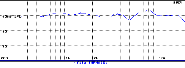
The first step is to measure the frequency response of the speaker, which is shown to the left. The response curve must be save.
(Note that the response shown here may be a little different from the response shown on the "How to measure a series crossover" page since the mic postion was not exactly the same.)
|
|
|
|
|
|
 |
|
|
|
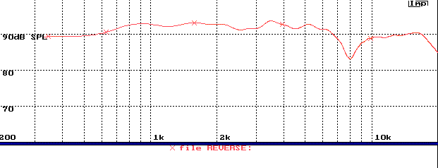
The next step is to measure the system again, but this time with the polarity of the driver that is to be removed from the response reversed. In this case we want to obtain the woofer output, thus the tweeter polarity is reversed. This result is shown to the left. This response must also be saved. |
|
|
|
|
|
 |
|
|
|
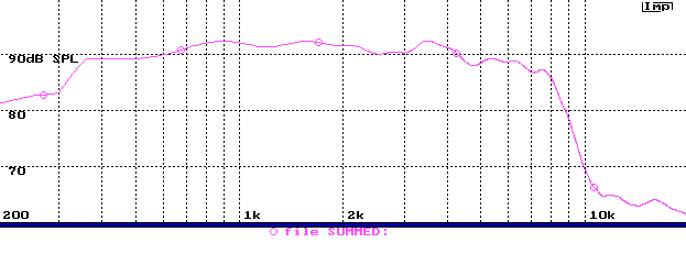
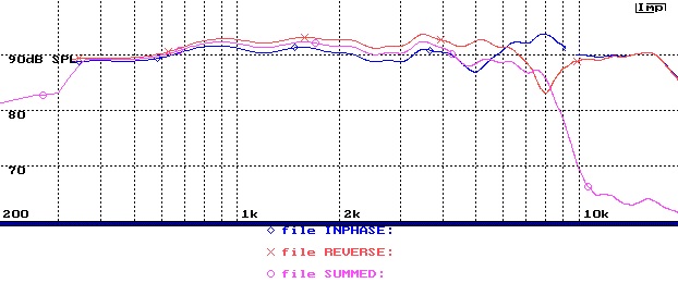
The final step is to sum the two response data files saved in the first 2 steps and scale the result by -6dB. In the IMP this is done using the Transfrom/Merge menu options. Similar operations can be done in LAUD. Alternatively, the sumation can be done using the FRC, as noted in the introduction, or in your speaker design software. The result, as shown to the left, is the acoustic output of the woofer connected to the crossover filter, without any contribution form the tweeter. |
|
|
|
|
|
 |
|
|
|
The figure to the left shows the three response curves overlaid. The response with the tweeter in phase is the blue curve; with tweeter polarity reversed, red; and the sum of the two is shown in violet.
While the result shown here is for a simple 2-way speaker using a series crossover, the procedure can be applied to any system. All that need be done is to make the two measurements. The first with all drivers connected correctly, the second with all the drivers connected with inverted polarity,with the exception of the driver of interest. It should be noted that for the procedure to work, the measurement system must obtain accurate amplitude and phase response data. |
|
|
|


