A 3-Way, Minimum Phase Speaker System using the Vifa PL14WJ-09, M11WH-09 and the Scan Speak D2905/9300

The results below are based on CAD simulations made using Sound Easy to model a 3-way speaker system that retains a minimum phase response, thus is transient accurate, within the limitations of the low frequency roll off of the system. The speaker is based on the crossover concepts originally presented by B&O in 1977, and employs second order Butterworth acoustic filters for the woofer and tweeter. The coupling or filler driver, the M11, uses an acoustic, 1st order band pass filter. While the results presented below are only simulations, they are based on actual SPL and impedance measurements of the selected drivers. In view of the excellent agrement between simulation and measurement for numerious other systems I have designed, I have no reservations with regard to the performance of this system upon being built. The key to obtaining these results was careful and critical matching of the drivers' acoust response to the target response of the required filters. As such, the crossover topology is somewhat complex. I am currently investigating means of simplifing the topology.
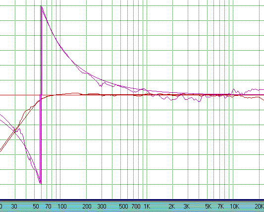
< Amplitude and phase response.of the system compared with a 4th order Buterworth high pass filter response with F3 = 60. Hz. Note the excellent amplitude and phase agreement indicating a minimum phase response.
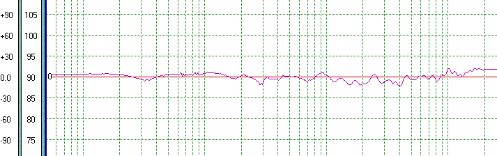
<Phase response of the system with the woofer response artificially extended to DC. Compared to the figure above, this result shows the affect of the low frequency roll off of the system on the phase response.
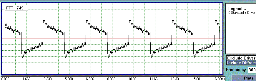
<Simulated on axis reproduction of a 300 Hz square wave. Note the excellent rise and fall of the wave. The tilt in the wave form is due to the low frequency roll off of the system and the resulting phase shifts that extend into the lower midrange.
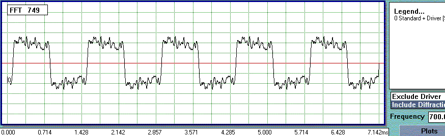
<Simulated on axis reproduction of a 700 Hz square wave. Note the much lower degree of tilt in the wave form as the frequency rises above the region where the roll off affects the phase significantly.The rise and fall are still excellent.
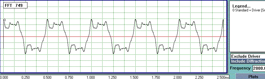
<Simulated on axis reproduction of a 2000 Hz square wave. Here the rise an fall start to show the high frequency limitations of the system.
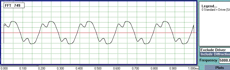
<This figure show the system reproduction of a 5000 Hz square wave. Here the wave is clearly distorted due to a lack of higher order harmonics.
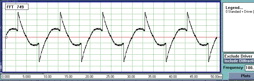
<A 100 Hz square wave is shown in this figure. The rise and fall are good, but the wave form is highly distorted due to the phase shif resulting from the low frequency roll off of the system. This is not a result of amplitude response irregularities.
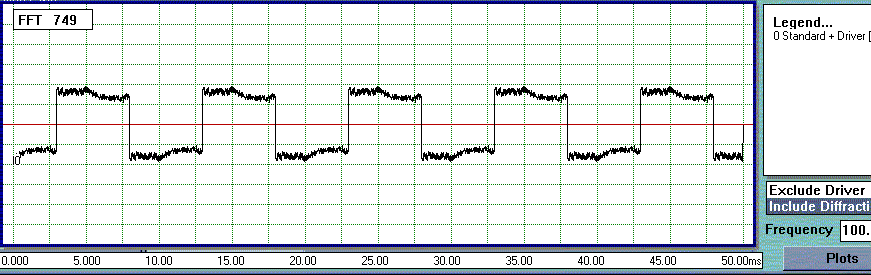
<This figure shows the response to a 100 Hz square wave when the system response is artificially extended flat to DC. The result serves as verification that the distortion shown in the figure above is indeed due to the phase shifts which arise due to the low frequency cut off.
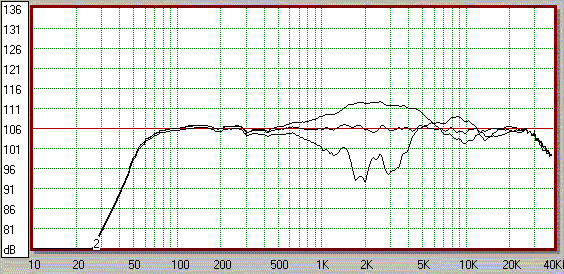
<This figure shows the response of the system at +/-15 degrees off axis in the vertical direction.when the drivers are aligned vertically as closely as the drivers' diameters allow.
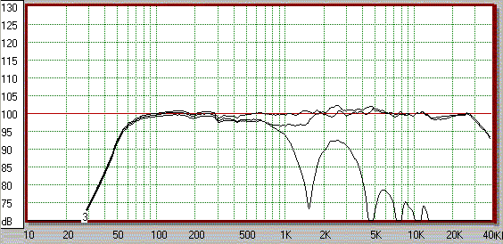
<This figure shows the +/-15 degrees response when the system is configured in an WFTFW arragement. Note the vastly imporved response. Additionally, note the response of the woofers alone (scalloped response) indicating that much of the response irregularity off axis, below 1K Hz, is due to the interaction between the woofers and not the filler driver concept.