
|
Second Order Crossover Networks |
See also First Order Crossover Networks
Building your own 2nd order passive Crossover network
In most cases, you will normally use a 1st order crossover for the woofer in a Pro-Audio environment. Usually most Pro-Audio (by this I mean high powered PA, Guitar, Keyboard and Monitor systems) speakers are not very flat in their frequency response curves, and as such, tuning them by using a tigher controlled crossover network doesn't always improve the sound very much, if at all. For high powered midrange horns, however, you can set the crossover frequency lower without worrying about too much power from the very low frequencies being passed thru the voice coil - this may improve your PA's vocals by helping them cut thru better.2nd order crossover networks roll off frequencies at 12db per octave, rather than 6db per octave as a 1st order does. This means that the frequencies that you choose for a specific speaker will get less of the frequencies that you don't want it to respond to. You may also find additional resonant frequency points introduced as a result of the impeadance interaction of the speaker, inductor and capacitor that you never got when using 1st order crossover networks - this is not a good thing, but often these new added peaks don't have serious effects.
You'll find that in most studio monitors and many higher end home audio speakers 2nd order crossovers are used and the manufacturer of these systems have painfully balenced the components to get the best and most accurate sound. This is not always the case for Pro-Audio gear and I see far more 1st order crossover networks used in Pro-Audio Gear.
As with 1st order crossovers, you can put woofers, midrange horns and tweeters all in the same cabinet, or you can put them in separate cabinets with their crossover components; it makes no difference, as long as you provide the right components for the frequency range you want.
The goal is always to match the speaker to the task it was designed for and make sure that you never apply frequencies inappropriately to speakers that cannot handle it.
2nd order crossovers are fairly simple to implement. The following diagrams show the schematic. There a 2 specific crossover components (L1 and C1) per speaker load. These 2 components, along with the speaker impeadance cause the frequency to roll off at the desired point.
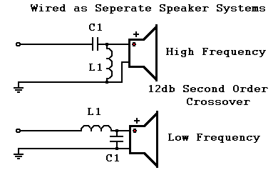
If wiring up separate components for specific functions
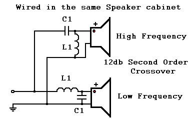
If enclosing separate components in a single unit
NOTE: each frequency range has its own specific L1 and C1
combination. This schematic implies that all the Capacitors
and Inductors are the same, but, you really choose the correct
L1/C1 combination for each speaker/frequency range needed.
Why would you wire things separately? You might have a Sub-Woofer; you don't install Tweeters in those very often. You might also have a large Midrange horn - this is probably in its own cabinet. No matter how you need to wire it, its quite easy to select the right crossover components.
Since each speaker will provide load at the specified frequency range, you need to calculate the loads at the given frequencies to make sure that you don't overload you amplifier. Cabinets that have all the speakers in the same place make it easier to calculate the loading effect as a single speaker. If you have a number of cabinets, each load must be accounted for. High frequency loading does not provide as significant an effect as low frequency loading - always make sure that your Woofers are accurately accounted for.
Crossover Capacitor/Inductor Selection Guide - 12db (2nd Order)
When you are ready to choose your crossover point, this chart indicates what frequency that relates to both the Low Frequency and the high Frequency components. Keep in mind that you may not be able to find an exact match when trying to purchase the Inductor or Capacitor. Try to find the closest matching parts (or use as many as needed) to get the frequency response you are shooting for. The chart lists values for both 8 ohm and 4 ohm cabinets/speaker systems. If you have a 16 ohm cabinet, divide the 8 ohm capactor values by 2 (for example, at 1000 Hz, the 8 ohm Capacitor is 14.0 uf, for 16 ohm systems, it would be 7.0 uf) and multiply the inductor value by 2 (the 1000 Hz 8 ohm Inductor is 1.8 mH, for 16 ohm systems it will be 3.6 mH).
|
Frequency |
Capacitor C1 |
Inductor L1 |
Capacitor C1 |
Inductor L1 |
|
|
|
|
|
|
|
|
|
|
|
|
|
|
|
|
|
|
|
|
|
|
|
|
|
|
|
|
|
|
|
|
|
|
|
|
|
|
|
|
|
|
|
|
|
|
|
|
|
|
|
|
|
|
|
|
|
|
|
|
|
|
|
|
|
|
|
|
|
|
|
|
|
|
|
|
|
|
|
|
|
|
|
|
|
|
|
|
|
|
|
|
|
|
|
|
|
|
|
|
|
|
|
|
|
|
|
|
|
|
|
|
|
|
|
|
|
|
|
|
|
|
|
|
|
|
What ratings should these parts have?
For Capacitors, the voltage that they can handle will determine how hard you can drive them:- 50 Volt Rating: 70 watts RMS
- 100 Volt Rating: 200 watts RMS
- 250 Volt Rating: 300 Watts RMS
Inductors for high powered systems will be made of solid copper wire, wrapped onto a plastic bobbin. For PA systems, they will be anywhere from 20 to 14 gauge wire. Always oversize inductors at least one size where possible.
- 20 gauge inductors cannot handle more than around 180 watts.
- 18 gauge inductors are usually good up to 250 watts.
- 16 gauge inductors are usually good up to 500 watts.
- 14 gauge inductors are usually good up to 800 watts.
Inductors have resistance, and can be checked with an ohm-meter. They typically run anywhere from 0.2 ohms (for .1 mH) to 1.3 ohms (for 10 mh).
Keep in mind that these power ratings relate the load an individual speaker will carry, not an entire system. If you have 4 speaker cabinets per side and 400 watts driving them, its likely that each cabinet will see 100 watts of power on average. This is what you need to scale for. Never drive your speakers harder than they are rated for - you will destroy them long before a properly sized crossover component.
What about 3 speaker systems?
The information given here implies that you can only use a low frequency speaker and a high frequency speaker. The truth is that you can add an additional higher frequency speaker by adding another inductor and capacitor, where the inductor now drives the midrange, and the capacitor drives the higher frequency speaker; in a sense, slapping another crossover network behind the first high frequency capacitor stage.For example, you can have the woofer/midrange crossover at 1000 Hz and then add another crossover for a tweeter at 5200 Hz. This is how most pre-packaged 3 speaker crossovers are made.
Exceptions to the rules
Piezo Tweeters appear as a capacitive load to your audio power amplifier, and their actual load is a function of frequency. They don't need a crossover capacitor (it won't hurt to use one, but its not necessary). Piezo tweeters typically cannot handle more than 50 to 75 watts, so you normally wire them up in series until the needed power rating is achieved. Many people also wire a 20 ohm, 20 watt power resistor in series with the Piezo tweeters to protect them.Since a Piezo tweeter can have frequency response up to 50 kHz (well beyond human hearing), they easily add sparkle to things that have high frequency overtones, like cymbals. Many people consider their sound harsh. I like them, but I don't use that many of them in my PA cabinets. Piezos can radiate high frequencies at high power so well, that they can damage your hearing without you noticing it. They are also highly directional - You may need a few to aim in different directions to properly disperse the sound.
Questions? Comments? Contact me.
 Return to Shavano Music Online Home page
© 1998 - Shavano Music Online