![]()

| Train Module Main Page | Circuitry | Assembly and Tuning | Parts List |
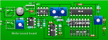
Parts List
RESISTANCES (all 1/4 W / 10%)
¤ R1,R9                100k
¤ R2                   820 ohms
¤ R3,R5,R11,R14,R15    1K
¤ R4 ,R19,R20          4.7K
¤ R6,R13,R18           10K trim pot PC mount
¤ R10                  300K
¤ R16                  18K
¤ R7,R8,R12,R17        10k
¤ R21                  1Meg
¤ R22                  680 ohms

CAPACITORS
¤ C1                   470uf/25 v, PC mount
¤ C2,C10               10uf
¤ C3                   .001 uf /polyester
¤ C4                   .068 uf
¤ C5,C7,C8              1 uf
¤ C12,C13              .1 uf
¤ C6,C15               .047 uf
¤ C11                  220 uf/25v , PC mount
¤ C14                  20 uf
¤ C9                   Not used

ICs
¤ IC1                  TIL 112 Opto Isolator 6 pins DIP
¤ IC2,IC7              741 Op Amp 8 pins DIP(or OpAmps of your choice,
                       not critical)
¤ IC3                  LM566 VCO 14 pins DIP
¤ IC4                  CD4017 CMOS Counter 14 pins DIP
¤ IC5                  LM386 Power Amplifier 8 pins DIP
¤ IC6                  LM556 Dual timer 14 pins DIP

Other Parts
¤ RT1,RT2              Rectifier bridge 50v/1A or 8 Rectifier diodes
                       rated 50v/5a
¤ VR                   Voltage Regulator 7812 pos 12 VDC/1A TO220
¤ ZD1                  Zener diode=1N704(4.1v 250mw) or 1N749(4.3v 400mw)
¤ D1 to D7             1N4148 diodes or equivalent(1N34)

¤ S1                   Small SPDT toggle
¤ Switch Horn switch   Small normally open push button switch
¤ Speaker              8 ohms, 2" to medium size
¤ Sockets              8 pins,4 ea
                       14 pins,3 ea

NOTE: For a power on indicator connect an LED in series with 1K
resistor across the supply bus AFTER the switch.
|
| Train Module Main Page | Circuitry | Assembly and Tuning | Parts List |
 |
|
 |
 |
Questions and comments to roma60@home.com
© Laurier Gendron, Burnaby, B.C., Canada. 1998