The design which includes research took us roughly 4 days. An advantage was gained due to a group member having previous experience in the design of power amplifiers. This reduced the time it took us to realize an optimum design.
The 2-Channel Power Amplifier:
Design and Testing
EE 498 Consumer Electronics
Professor: Kelin Khun
Group Members:
Canh Pham
Robin Phou
Hardy Widjaja
Design
The design of our power amplifier is based on a general purpose power amplifier widely used in the electronics world. The chip (NTE 1606) we are using is used in many consumer stereo systems. We did some research and came out with a simple design that uses the NTE 1606 Power Amplifier chip. The design is shown below.
The design which includes research took us roughly 4 days. An advantage
was gained due to a group member having previous experience in the design
of power amplifiers. This reduced the time it took us to realize an optimum
design.
Implementation
After we agreed on the design, we started implementing in hardware. The hardware implementation took 4 hours in total. Most of the time was spent to get the proper values for resistors and capacitors. The optimum values we chose made for better output.
The following is the list of the components of our power amplifier:
· Electronic Circuit Board
· IC NTE 1606 (can be seen clearly with its pinouts in Figure 1)
Figure 1
· Heat Sink
· Resistors (values:150-ohm)
· Capacitors (values: 1-mF, 0.1-uF, 1-uF, 100-uF)
Testing
Testing was the last process and the most time-consuming process of
all the processes. After completing the design in hardware, we did some
testing of the design using three distinct methods. We found that the circuit
was not right at first, so we did some debugging and some re-implementation
using different values for capacitors and resistors. The circuit worked
according to expectations after which we began obtaining the data results.
The following is the result of taking input from a tape player and setting
up a comparison of the input versus output on the Oscilloscope.
Note: Because of the working nature of the power amplifier, the output
waveform is inverted from the input waveform.

Figure 2.
Output comparison of Tape Audio input
As can be seen the output is significantly amplified from the input
signal taken.
Next we used a clean standard signal taken from the function generator
at lower frequencies. The following amplification can be observed although
minutely.
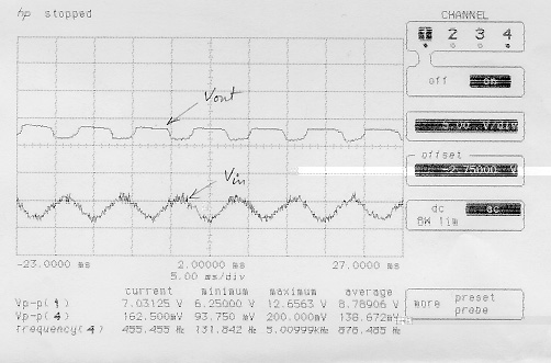
Figure 3. Output comparison of Function Generator input
The audio test was more of a subjective judge. Although the change in volume was very apparent when the amplifier was used, the actual result cannot be scientifically recorded.
The final range for the amplifier turned out to be from 5.5 Hz to 27 Khz.
Testing Equipment
· HP 3314A Function Generator
· HP 54501A 100MHz Digitilizing Oscilloscope
· Walkman, Panasonic.
· HP 6236B Triple Output 12-V power supply
· Speakers, 8-ohm, 100-watt
Some specifications
The circuit is powered by a 12V, 10-Amp power supply. The power of the output channels is 4 W connected to 8-ohm loudspeakers