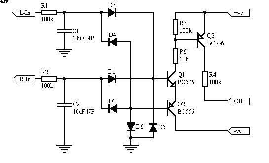
Figure 1 - Basic DC Detector
Circuit

| Elliott Sound Products | Project 33 |
Please see UPDATE 1, UPDATE 2 and UPDATE 3 on this project.
Many hi-fi amplifiers and professional power amps (and loudspeaker systems) provide some of protection, either to protect the speakers from an amp fault, and/or vice versa. Some of these are implemented at a very basic level - for example the use of a "poly-switch". The poly-switch is a non-linear resistor, having a low resistance at normal temperatures and a much higher resistance at some designated temperature. Unlike "ordinary" thermistors whose characteristics are more or less linear, the poly switch has a rapid transition once the limit has been reached.
I don't like poly-switches, because I know that the introduction of a non-linear element is going to add some degree of distortion, and because of a finite resistance, will degrade damping. This (i.e. damping) is not an issue IMHO, but to many audiophiles it is of prime importance. (I shall not pursue this argument here, however - see Impedance for more info.)
The basic requirement of a speaker protector requires that any potentially dangerous DC flow to the speakers should be interrupted as quickly as possible. There are a few issues that need to be solved to ensure that this will happen fast enough to stop the loudspeaker drivers from being damaged, and this becomes more critical if a biamped (and even more so with triamped) system is being used.
Naturally, one can simply rely on fuses. Although these also have finite resistance it is small, and use of fast blow fuses can be quite effective. The rating becomes quite critical, and fast blow types are essential. The problem with this approach is that if the fuse is of a suitable value to provide good protection, it will be subjected to considerable thermal stress since it is operating at close to its limits. Metal fatigue will create the problem of nuisance blowing, where the fuse blows simply because it is "tired" of the constant flexing caused by temperature variations.
This project explains the principles, and shows a suitable detection method that may be applied. The speed of the relay used is another critical factor, and we shall see that the conventional method of preventing the relay's back-emf from destroying the drive transistor also slows down the response to an unacceptable degree.
The circuit also includes a mute function, which leaves the speakers disconnected until the amplifier has settled, and disconnects the speakers as quickly as possible after power is removed to prevent the turn-off noises that some amps generate. These can range from a low level thump 5 to 10 seconds after power is turned off, to whistles, squeaks and other strange noises that I have heard from amps over the years.
It is important to identify the lowest frequency likely to be passed to a speaker, because this determines the delay that must be introduced to prevent low frequencies from triggering the protection circuit (nuisance tripping). For practical purposes, a low frequency limit of 20Hz is satisfactory for a full range system, and this means that a minimum 25ms delay is essential. In reality, due to the combination of low frequencies, and asymmetrical waveforms at higher frequencies, a greater delay will normally be required. Unfortunately, the greater the delay, the greater the risk of drivers being damaged. In a full range system (i.e. using passive crossovers), midrange and tweeters will be offered some protection by the capacitors used in the crossover network, but these are missing in a biamped or triamped system. For this reason, it is important that the circuit can be easily modified to change the initial time delay before the system detects the DC and disconnects the speakers.
The Detector
This is the most important of the functions.
It must be capable of detecting a DC offset of either polarity, and be
immune to the effects of asymmetrical waveforms and low frequencies.
This is a common requirement, and it is most expedient to use a simple
(single pole) filter to keep the complexity to a minimum. With this
arrangement, a low frequency cut-off of about 0.1Hz is about right.
Without boring you with the mathematics behind this, it works out (eventually)
that a filter having a time constant of 1.0s will still provide the ability
to detect high level DC reasonably quickly, but allow low frequencies through
without triggering. With this, the relay could have its supply removed
within about 50ms from the time the output voltage reaches the supply rail
(this is supply voltage dependent) - due typically to a shorted transistor
in the output stage. By changing the time constant of the filter,
we can adapt the circuit for operation at other higher frequencies to suit
a biamped (or triamped) system.
The detector can be built using an opamp, and will work very well, but this introduces the need for low voltage supplies within the power amp. This is not always possible (or desirable), so the design uses discrete transistors throughout to allow for the different supply voltages found in typical power amplifiers.
The detector circuit shown in Figure 1 (1) is simple and works well, and as shown will not trigger with a 30V RMS signal at 5Hz, but operates in 60ms with 30V DC applied, and in 50mS with a 45V DC supply. This should be sufficient for most applications, and allows the use of a non-polarised electrolytic capacitor in the filter. These are cheap, small and quite adequate for this purpose.
NOTE: The power supplies (+ve and -ve) shown in these diagrams will normally be the power amp supply rails. Do not try to substitute different supplies unless you know exactly what you are doing, or the circuit may not work properly. This is especially true of the muting circuit, but incorrect supplies will (may) also affect the DC detection circuit. Like most of my projects, this is intended for experienced constructors.
UPDATE: The original circuit could damage Q3 under some conditions due to excess base current. To remedy this, a resistor must be added between the collector of Q1 and the base of Q3, as shown in the amended diagram. This prevents excess base current if the gain of Q1 or Q2 is higher than expected. My thanks to Vince (a reader) for pointing this out.

Figure 1 - Basic DC Detector
Circuit
Note that using a two pole filter will actually degrade the DC detection. This basic circuit is not new (see reference), and has actually existed in one form or another for some time. It is ideally suited for our requirements, as it is symmetrical, and with the input diodes as shown, a single detector can be used with multiple amps and different input time constants for each individual filter. The unit itself can operate on a separate supply if desired, so the complete protection circuit can be in a separate enclosure. Regulated supplies are not needed, and no hum or other "artefacts" are introduced into the speaker lines. (Please see NOTE above.)
The table (below) shows some suggested
values for the filter, for use in bi- and tri-amped systems. You
will need one filter and two diodes for each amplifier channel connected,
and a suitable number of relay contacts to handle them all. In some
cases, this will mean multiple relays.
| Frequency (Hz) | C1 Value |
| Full Range | 10 uF (non-polarised) |
| 100 Hz | 1 uF |
| 300 Hz | 330 nF |
| 1 kHz | 100 nF |
| 3 kHz | 33 nF |
The resistor should be left at 100k for all frequencies. Do not use a conventional electrolytic capacitor for C1, because any small reverse bias will eventually ruin it. You may discover that with some types of music (especially if at high volume) may cause the circuit to false trigger. If this happens, increase the value of C1, up to a maximum of 47uF. Anything higher than this will slow down the response unacceptably.
Relay Specifications
The relays should be easy enough to obtain.
At least one of the Australian component suppliers has relays that are
quite suitable, but they are not particularly cheap. The current
rating is very important, and assuming a supply voltage of +/- 40V, this
will cause a current of about 6A in an 8 ohm speaker if a transistor shorts.
Although 6A may not sound like much, it is at DC, and because there are
no periods of 0V as with AC, the arc is longer, fatter, and far more destructive
of contacts than the same current using AC.
Do not be tempted to use miniature relays, because if the normal AC speaker signal is too far in excess of the relay contact rating, the contacts may become welded together - this will almost certainly happen if the DC rating is too low. You also need to consider that contact resistance is additional resistance in the speaker lead and may affect damping (albeit very marginally) and will introduce some small power loss, and the miniature types will not be suitable in this regard.
I had a look in the catalogue of one Australian supplier, and they have several relays with a 10A contact rating. I would suggest that anything lower is unwise for long term reliability. Most of the commonly available relays will have a 12V coil, and this will cause problems if the supply voltage is 30V or more. Power relays often draw significant current (typically > 60mA), and it will usually be best to connect the coils in series.
UPDATE: A reader (I cannot recall who it was so I can't give the credit) mentioned that in some areas there is significant sulphur content in the air, and this causes heavy tarnishing of silver contacts. If you live in such an area, it would be advisable to obtain hermetically sealed relays if possible, to prevent the contacts from tarnishing.
It is well known that the current required to activate a relay is far greater than that needed to keep the contacts closed, and a common trick is to use an "efficiency" circuit to minimise the relay holding current. I do not feel that the additional complexity is warranted, and have not included this facility. If you really want to do this properly, see reference 1 (below). It has been claimed that an efficiency circuit also speeds up relay drop-out time because of the lower stored magnetic field. I conducted some tests, and the savings are marginal at best, although this could be different with different relays.
Figure 2 shows the relay activation circuit, and includes the connection for the mute and protection signals. No components are critical, but some will need to be modified based on the relays used. I have assumed that a minimum of two relays will be needed (one for each channel), and this increases the total relay coil voltage to 24V. If you are going to use more than two (for example, four single pole relays are needed for a biamped system), then if the supply voltage is 48V or more, all 4 relays can be connected in series. In most cases you will need to work out the value of a suitable dropping resistor from the formula below.
The terminal labelled "Off" is common to all three modules, and these points are simply joined together, as are the +ve and -ve supply connections. A positive current into the Off terminal will de-energise the relays, by turning on Q1. This steals all the base current for Q2, which then turns off, as does Q3.
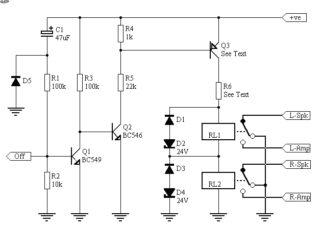
Figure 2 - Relay Activation
Circuit
The relay(s) must be turned off in the shortest possible time, so the use of the normal protection diode across the coil should not be used, as it slows the response considerably. Instead, the arrangement shown still protects the driver transistor, but allows the relay magnetic field to collapse without generating a current in the coil (this the what slows the relay's release). I cannot predict the exact delay you will achieve, since the choice of a suitable relay is outside my control. You will have to pester and annoy your local suppliers to find a relay that has suitable characteristics, and be prepared to pay what will seem like an obscene amount of money for a simple electro-mechanical device.
D5 (a late addition) will discharge C1 as the supply collapses. It will not help much in the case where someone switches the power off then straight back on (not that anyone would do that!), but will reset the circuit much faster than would otherwise be the case. My thanks to Vince for the idea.
UPDATE - 10 Aug
2000
It has been brought to my attention that
the DC arc can (and does) destroy even 10A relays under some circumstances.
To provide greater speaker protection, the relay wiring in Figure 2 has
been modified to short the speaker to earth in case of a fault. This
way, even if the contacts do arc it will be directly to earth. This
is much safer (for the speakers), and the arc to earth will blow the fuse
a lot faster than if an 8 ohm load is a part of the circuit. It is
strongly recommended that this new scheme is used as a matter of course.
(My thanks to Phil Allison for the information.)
Note also that this circuit cannot be used as shown with the 12V relays in series if the supply voltage is less than +/-24V (but you knew that already).
In order to work out the value of R6, subtract the combined relay voltage from the supply voltage (you must know the relay coil current!). To calculate the coil current from its resistance, use the following (I have assumed a 40V supply for the examples):
I = V / R Where V = coil voltage and R = coil resistanceSo for a 180 ohm coil (fairly typical) this works out to
I = 12 / 180 = 67mAThe resistor value is worked out with:
R = V / I Where V = the "left over" voltage from the subtraction and I = coil currentYou will also need to work out the power rating for the resistor:
P = V2 / R Where V is the voltage and R is the resistanceAgain, for the above example, this works out to
R = ( 40 - 24 ) / 67mA = 16 / 0.067 = 239 Ohms (220R should be fine)So for an adequate safety margin, a 2 Watt resistor should be considered the minimum (5W would be better).
P = ( 16 x 16 ) / 220 = 1.16W
To determine the transistor for Q3, add the supply voltage and the zener voltages to give the maximum collector to emitter voltage. In this case it is 40 + 48 = 88 Volts, and I would suggest that a transistor with a breakdown voltage of at least 100V be used to give some safety margin. The MJ350 (300V rated) will be suitable in nearly (if not) all applications, or you can use a MPSA92 - lower current, but still has a 300V rating.
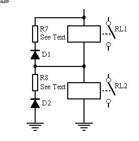
Figure 16a - Alternative
Back-EMF protection
Figure 16a shows an alternative method you can use to damp the back-emf from the relay, but to implement it properly, access to an oscilloscope is helpful (if not essential). If the resistors have approximately the same resistance as the relay coils, the back-emf should (!) be limited to about the normal relay voltage, give or take 50% or so. In the tests I carried out (see Tests, below) using a 24V relay, the back-emf was limited to about -30V, which would be fine in most cases.
This method is slightly cheaper than using
zeners, but is less predictable. An additional alternative is to
use a catch diode to the -ve power supply. A 1N4004 between the top
of the relay string and the -ve amp supply will limit the back-emf to the
voltage of the -ve supply, so for the example case this would be -40V.
I expect that this would be quite acceptable, but have not tried it.
Make sure that the diode is connected the right way around - the cathode
goes to the top of the relays, and the anode to the negative supply.
Muting
Since we have all this new circuitry,
it is most worthwhile to incorporate a muting function, so that when power
is removed from the system, the relay will open to stop turn-off transients
from being heard. Likewise, we will normally want to mute the system
for about 2 seconds after power is applied to stop the turn-on transients
as well. C1 and R1 in the circuit of Figure 2 provide the turn-on
delay, by supplying current to the "Off" terminal as C1 charges.
Once charged, the current falls to zero, and Q1 turns off, allowing Q2
and Q3 to turn on, thus energising the relays. (Note that this timer
will not be reset if the power is turned off and back on again quickly,
but since this is a procedure that should be avoided anyway, no provision
has been made for it. :-)
To be able to do this effectively, we must have access to the AC from the power amp's transformer, or have the external unit controlled by the main power switch in the system. In some hi-fi installations, there will be a multiplicity of different units to turn on (and off) each time the system is used. I will leave it to the reader to decide which unit to use as the control, but would suggest that where a separate preamp is used, this could be an ideal controller for the entire system. It is unfortunate that hi-fi has not followed the sensible approach of a lot of computers, with a switched IEC connector on the back of the preamp to control power amps and other outboard devices. (I did this on my VP-103 valve preamp, and it is most useful :-)
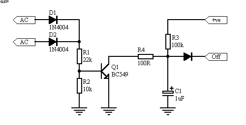
Figure 3 - Loss of AC
Detector
The power detector cannot rely on the DC supply, as this may take a considerable time to collapse. The common approach is to use a rectified but unsmoothed output from the transformer secondary. Because it is not smoothed, this disappears instantly when power is removed, and is ideal. Figure 3 shows the basic circuit, and this will remove relay drive within about 50ms of the power being turned off. We could make it faster than this, but there is little point.
The circuit simply uses the current pulses to keep a capacitor discharged via Q1. When the pulses stop, the cap charges until the threshold voltage of the "Off" terminal is reached (0.65V), and the relays are turned off. After power is first applied, the timer circuit will activate the relays after about 4 seconds (typical). This can be increased if desired, by increasing the value of C1 in Figure 2.
I carried out some tests to see just how quickly the relays could be operated. The results were something of an eye-opener (and I knew about the added delay caused by a diode!). The relay I used was a small 24V coil unit, having a 730 Ohm coil and with substantial contacts (at least 10 Amps). With no back-emf protection, the relay opened the contacts in 1.2ms - this is much faster than I expected, but the back-emf went straight off the scale on my oscilloscope, and I would guess that the voltage was in excess of 500V. When a diode was added, the drop-out time dragged out to 7.2ms, which is a considerable increase, and of course there was no back-emf (Ok, there was 0.65V, but we can ignore that). Using the diode / resistor method described above, release time was 3.5ms, and the maximum back-emf was -30V, so this seems to be a suitable compromise.
I was not able to test the zener method prior to publication, since I did not have the 24V zeners needed on hand. I would expect this scheme to be as good or better than the diode / resistor combination. The graphs below show the behaviour of the circuit with and without the resistor and diode. The estimated 500V or more is quite typical of all relays, which is why the diode is always included. This sort of voltage will destroy most transistors instantly. It is exactly the same process used in the standard "Kettering" ignition system used in cars, but without the secondary winding, or the "flyback" transformer used in the horizontal output section of a TV set.
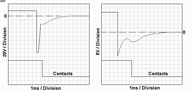
Figure 4 - Relay Voltages
The trace labelled "Contacts" is representative only, and is not to scale. The peak relay voltage (above left) exceeded my oscilloscope's input range (and I was too lazy to set up an external attenuator), and as shown is cut off at my measurement limit. I estimate that the voltage is greater than 500V.
Note that the kink in the relay voltage curve is caused by the armature (the bit that moves) coming away from the relay pole piece, and reducing the inductance. This causes the stored magnetic "charge" to try to increase the voltage again, but it is absorbed by the resistance and dissipated quickly. The contacts open at the point where the previously closed magnetic field is opened as the armature moves away from the pole piece. As can be seen, this is 3.5ms after the relay supply is disconnected.
These graphs are representative only, as different relays will have different characteristics. As noted above, I cannot predict what sort of relay you will be able to obtain, but the behaviour can be expected to be similar to that shown. All tests were conducted using a 24V relay, having 10A contacts. Upon contact closure, I also measured 2.5ms of contact bounce. Provided your amplifier is stable by the time the contacts close, this will be completely inaudible.
| Copyright Notice. This article, including but not limited to all text and diagrams, is the intellectual property of Rod Elliott, and is Copyright (c) 1999 - 2000. Reproduction or re-publication by any means whatsoever, whether electronic, mechanical or electro- mechanical, is strictly prohibited under International Copyright laws. The author (Rod Elliott) grants the reader the right to use this information for personal use only, and further allows that one (1) copy may be made for reference while constructing the project. Commercial use is prohibited without express written authorisation from Rod Elliott. |